- Motion Control
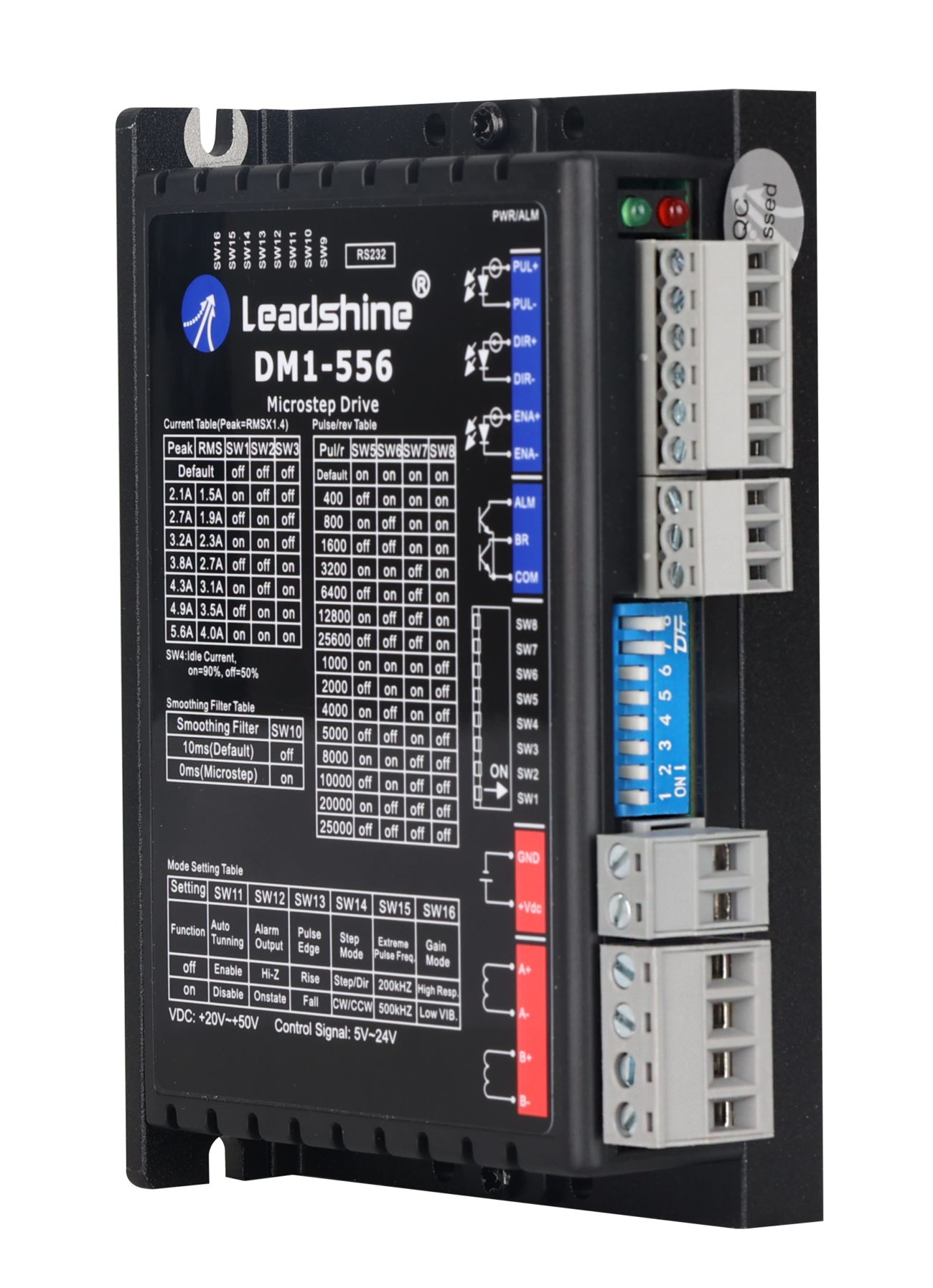
- Leadshine IDM Series Integrated Smart Motor with Driver | Compact, Plug-and-Play, High Acceleration, Easy Installation
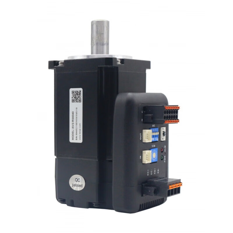
- ISV2 Series Intelligent Integrated Low Voltage Servo Motor – CANopen & RS485 Communication For Automation Solution
- Integrated Closed-Loop Stepper Motor Series Stepper motor + Drive + Controller
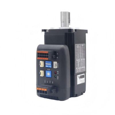
- Leadshine 5-Phase Stepper Motors Low Vibration for Optical Communication Modules
- Leadshine 57CME Series Closed Loop Stepper Motor | High Torque Low Heat High Stability & Consistent Performance for Precision Machine
- Leadshine 57CM Series NEMA23 Stepper Motor | High Torque Low Heat High Consistency 0.6-3.1Nm
- Leadshine MC500 PLC | EtherCAT 32-Axis Motion Controller with Dual-Core, IEC 6 Languages for 3C, PV, Lithium Battery, Logistics & Packaging Automation
- Leadshine LC Series Large PLC Controller – CODESYS Platform 256-Axis EtherCAT Motion Controller
- R Series EtherCAT Remote I/O Modules for Flexible and Scalable Industrial Automation
- Siemens AC Servo Motors | High Precision Closed-Loop Motion Control, Synchronous & Induction Motors for Robotics, CNC Machine Tools, Packaging and Semiconductor Equipment
- Panasonic MINAS A6/A7 Series AC Servo Motor 50W-22kW – 23bit Encoder, 3x Overload, IP67, 3.2kHz Response, PLC Compatible for High-Precision Industrial Automation
- Delta Servo Systems Delta PLC
- Linear Motion Module
- Precision Ball Screw Linear Slide Module
- High Precision Ball Screw Slide Table Heavy Duty Linear Module for Industrial Automation CNC Equipment Parts
- Cleanroom Ball Screw Linear Module, Low Particle Release High Rigidity Dustless Linear Actuator for Semiconductor Medical Industrial Automation Equipment
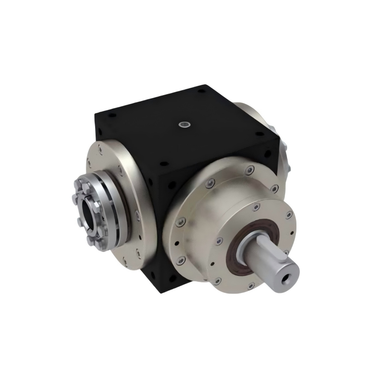
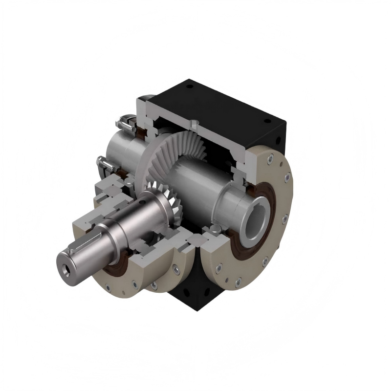
- Industrial Gear Reducer
- High Precision Planetary Gear Reducer With Low Backlash, High Torque Density for Robotics & CNC Automation
- Helical Gear Reducer – Low Noise Heavy Duty Modular Design Industrial Gearbox with Easy Maintenance
- Industrial Modular Helical Gear Reducer – Smooth Transmission, Strong Overload Resistance & Flexible Mounting, Suitable for Chemical, Textile & Heavy-Duty Equipment
- Robotic Arm
- Vision & Sensor Systems
- SICK Vision Sensor for High-Precision Machine High Accuracy Detection & Positioning for Smart Factories & Robotics
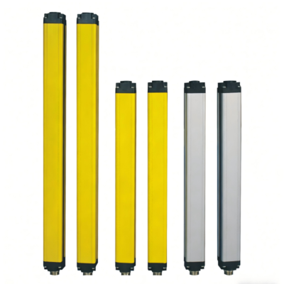
- SICK Photoelectric Sensor Safety Light Curtains – IP67 Safety Protection for Machine Guarding
- Hikvision CU Series Cost-Effective Industrial Camera Built-in ISP Algorithm with WDR GigE Vision & USB3.0 Interface for Industrial Machine Vision
- Pneumatic Components
- Airtac Air Source Treatment Three-in-One Unit Preparation Units Filter Regulator & Lubricator for Industrial Automation Systems
- AIRTAC Solenoid Valve | Direct/Semi-Direct/Pilot Operated, Leak-Proof & Explosion-Proof DN50, Industrial Fluid Control for Automation, Chemical & Mechanical Piping
- Pneumatic Slide Table Cylinder – ±0.01mm Precision Compact Integrated High Rigidity Durable for Automation
Hot
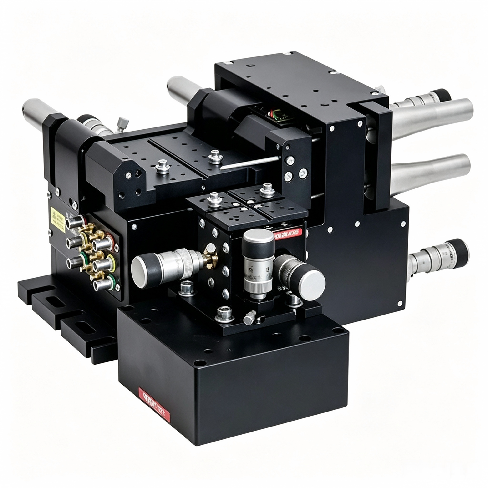
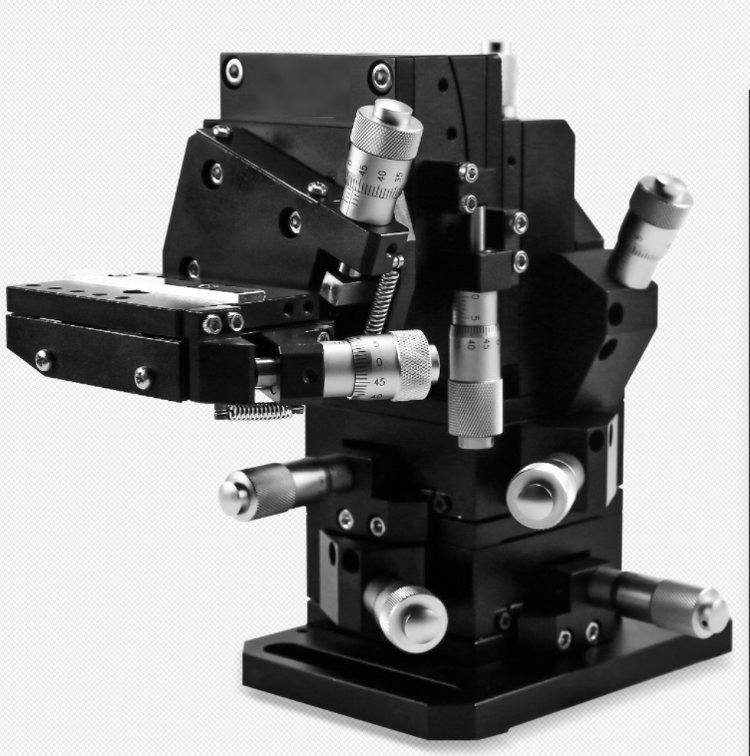
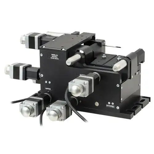
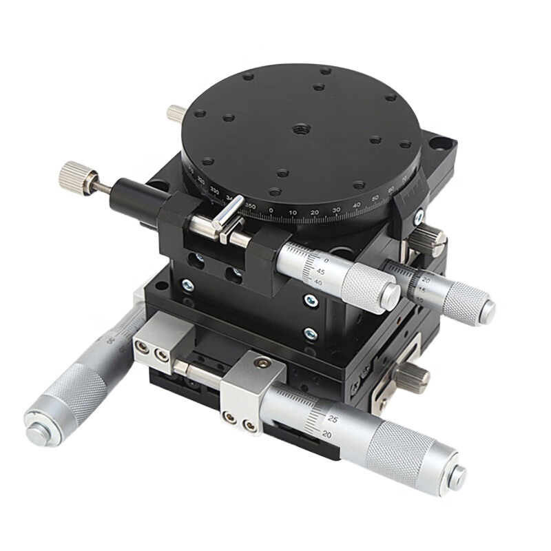
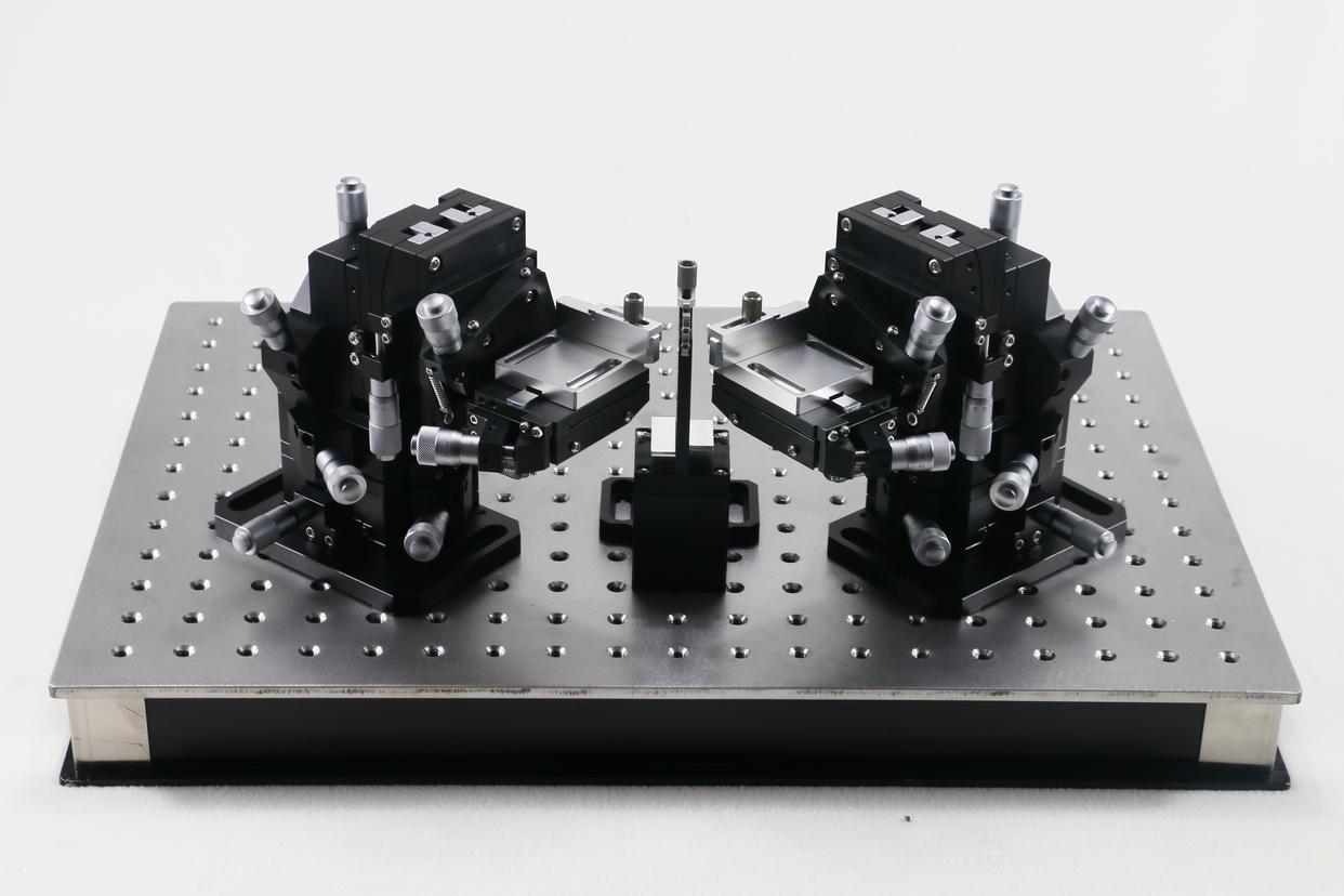
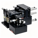
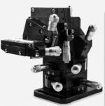
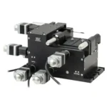
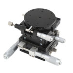
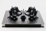
Precision Multi-Axis Manual Positioning Stages For Fiber Alignment Stages
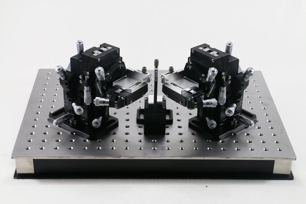
Designed for advanced fiber alignment, optical coupling and precision positioning, our High-Precision XYZ Multi-Axis Fiber Alignment Stages combine direct-drive linear motor technology, anti-creep crossed-roller guides and a compact multi-axis architecture to deliver fast, smooth and highly stable XYZ motion.
Precision-machined from lightweight aluminum alloy with a black anodized surface, the stages combine a compact multi-axis structure, crossed-roller guideways, micrometer-head adjustment, and spring-return preload to provide smooth motion, reliable positioning, and convenient operation.
The integrated XYZ structure enables precise adjustment along three orthogonal axes within a compact footprint, making the stages particularly suitable for optical experiments, photonics research, microscopy, inspection systems, precision measurement, and applications where space is limited.
Standard mounting-hole patterns on the stage and base simplify installation and allow easy combination with optical components, fixtures, sensors, and other positioning devices.
Core Advantages
- High-Precision Manual Positioning
- Precision Crossed-Roller Guides
- Low-Backlash Adjustment
- Compact Multi-Axis Design
- Lightweight Aluminum Construction
- Flexible Micrometer Configuration
- Easy Installation & System Integration
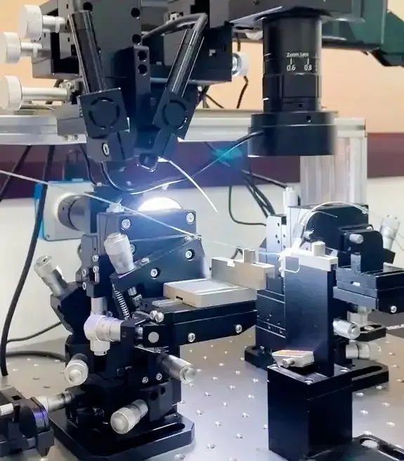
Working Principle & Performance Specifications
High-precision positioning between optical fibers and optical components is the decisive factor for coupling efficiency. Whether for laser chip-fiber coupling, fiber array docking with waveguide chips, or optical path matching between fibers and photodetectors, delicate fine-tuning is required to lock the optimal coupling operating point.
During practical commissioning, engineers continuously adjust the spatial posture of fibers according to real-time optical power readings to achieve maximum optical transmission efficiency. The motorized 6DOF stage covers all six degrees of freedom for fine adjustment, enabling precise control over fiber horizontal/vertical/axial position, pitch, yaw and rotational posture, which effectively shortens the debugging cycle of fiber coupling systems.
Traditional pure XYZ translation stages only execute linear displacement; once tilt deviation or optical axis misalignment exists on fiber end faces, translational adjustment alone cannot reach the optimal coupling state. Actual fiber coupling processes demand compensation for end-face inclination and axial rotation errors besides spatial movement.
The integrated XYZ-θX-θY-θZ structure allows synchronous fine-tuning of linear displacement and angular deflection, perfectly fitting fiber end faces to target optical paths and lowering optical insertion loss remarkably.
Motorized Linear Stage VS Manual Linear Stage— Comparison
| Motorized Linear Stage VS Manual Linear Stage— Comparison | |||
| Comparison Dimension | Manual Linear Stage | Motorized Linear Stage | Best Suited For |
| Power Supply | No power required; fully hand-operated | Requires external power supply and motor driver | Manual: field / lab setups without power; Motorized: automated production lines |
| Electromagnetic Interference (EMI) | Zero EMI; no circuit noise, ideal for weak laser / fiber signals | Generates EMI and electrical noise that may interfere with sensitive optical signals | Manual: photonics, fiber coupling, optical alignment; Motorized: non-optical automation |
| Positioning Accuracy | Micron-level via micrometer screw / differential head; depends on operator skill | Sub-micron to nanometer repeatability with closed-loop encoder feedback | Manual: static precision calibration; Motorized: high-repeatability dynamic positioning |
| Control Method | Handwheel / micrometer manual adjustment; DIP or mechanical lock | Pulse / IO / bus control via PLC, motion controller or PC software | Manual: simple one-off adjustment; Motorized: programmable multi-axis motion |
| Automation Level | Manual only; no automated cycles | Fully automated; supports program recipes, batch cycles and remote control | Manual: R&D, prototyping, low-volume; Motorized: mass production, 24/7 operation |
| Motion Speed | Low; limited by manual turning speed | High; configurable velocity, acceleration and trapezoidal motion profiles | Manual: static alignment; Motorized: high-throughput pick & place, scanning |
| Cost | Low cost; simple mechanical structure, no electronics | Higher cost; includes motor, encoder, driver and controller | Manual: budget-sensitive labs / startups; Motorized: ROI-driven production |
| Footprint & Integration | Compact, lightweight, easy to stack and integrate into optical breadboards | Larger due to motor, coupling and cable management; requires wiring | Manual: space-limited optical benches; Motorized: cabinet / gantry systems |
| Programming Required | No programming; plug-and-play mechanical operation | Requires parameter tuning, motion programming and driver configuration | Manual: users without motion-control expertise; Motorized: engineering teams |
| Heat Generation | No heat generation during operation | Motor and driver generate heat; may require cooling in long-run scenarios | Manual: thermally sensitive optical experiments; Motorized: general automation |
| Response Time | Slow; depends on operator reaction and handwheel turns | Fast; millisecond-level response to control signals | Manual: non-time-critical setup; Motorized: real-time / high-cycle tasks |
| Load Capacity | Low to medium; constrained by manual drive torque and structure | Medium to high; motor torque supports heavier payloads | Manual: light optical components; Motorized: heavy fixtures / multi-axis stages |
| Repeatability | Moderate; operator-dependent, lower batch consistency | Excellent; closed-loop feedback ensures high batch-to-batch repeatability | Manual: single-point calibration; Motorized: repetitive manufacturing steps |
| Maintenance | Minimal; periodic lubrication of guide rail only | More maintenance; motor, encoder, driver and cabling require periodic check | Manual: long-life low-upkeep use; Motorized: scheduled maintenance programs |
| Typical Applications | Optical experiments, fiber coupling, laser alignment, university labs, semiconductor wafer manual fine-tuning, biomedical microscopy | Automated inspection, 3C assembly, laser engraving, PV / lithium battery production, semiconductor handling, CNC machining | Choose based on automation need, EMI sensitivity and throughput target |
| Ideal Use Case Summary | Precision static alignment where EMI-free, low-cost and compact manual tuning is prioritized | Dynamic, high-throughput, programmable positioning where speed and repeatability dominate | — |
Core Performance
- Motion Freedom: 6DOF (XYZ Linear Translation + θX/θY/θZ Angular Tilt & Rotation)
- Driving Mode: Closed-loop servo motor drive
- Linear Resolution: Sub-micron fine-tuning precision
- Angular Resolution: Micro-degree deflection accuracy
- Mechanical Design: Anti-backlash rigid structure, no posture drift post locking
- Control Method: PC programmable automatic scanning alignment
- Applicable Objects: Single fiber, lensed fiber, multi-channel fiber arrays
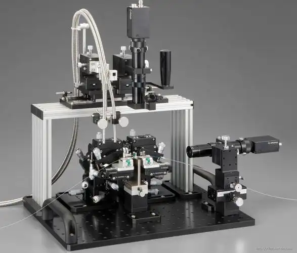
Core Competitive Advantages
1. Break the Limitations of Traditional 3-Axis Translation Stages
Pure XYZ platforms only realize spatial movement without angular compensation. This motorized 6DOF stage synchronously calibrates position, tilt and rotational deviation to eliminate extra coupling loss triggered by tiny optical axis misalignment.
2. Cut Optical Debugging Time Significantly
Combined with real-time optical power feedback, the system automatically searches for the peak optical power point, eliminating repeated manual fixture adjustment and trial-and-error work. R&D debugging efficiency is substantially lifted.
3. Superior Repeat Positioning & Locking Stability
Optimized rigid mechanical structure eliminates backlash and locking displacement drift. Test data stays consistent during repeated debugging, ensuring reliable experimental outcomes and uniform finished products in mass production.
4. Flexible Configuration for Diversified Photonics Processes
Supports freely configurable optical layouts to fit varied precision demands: high-efficiency laser-fiber coupling for optical modules, high-precision fiber array-waveguide docking for silicon photonics, and long-term stable multi-channel interconnection for photonic chip packaging.
5. Seamless Integration Into Automated Fiber Coupling Production Lines
Compatible with optical power meters, machine vision positioning systems, automatic dispensing units and UVLED curing equipment, forming a full closed-loop workflow: fiber positioning → optimal coupling searching → dispensing fixation → process inspection. Real-time optical power feedback speeds up production tact time, reduces manual repeated adjustment and improves batch product consistency.
6. Future-Proof for High-Speed Optical Communication Evolution
Adapts to the industry trend toward high precision, multi-channel layout and full automation, perfectly matching the manufacturing demands of 400G/800G optical modules, CPO co-packaged optics and silicon photonics.
Application Scenarios
- High-Speed Optical Module Packaging
400G/800G transceiver assembly, TOSA & ROSA component fabrication, laser-fiber active alignment
- Passive Optical Component Calibration
PLC optical splitter coupling, AWG arrayed waveguide device testing and performance tuning
- Silicon Photonics & PIC Chip Verification
Fiber array alignment with waveguide chips, edge/grating coupling testing, wafer-level optical characterization
- CPO Co-Packaged Optics Prototyping & Manufacturing
Multi-channel automated fiber alignment for next-generation AI data center optical engines
- Laser Diode & Photodetector Packaging
Precise coupling between laser chips, detectors and optical fibers
- Academic Precision Optics Research
Custom optical system construction, microscopic optical path debugging and frontier photonics prototype verification
Technical Parameters
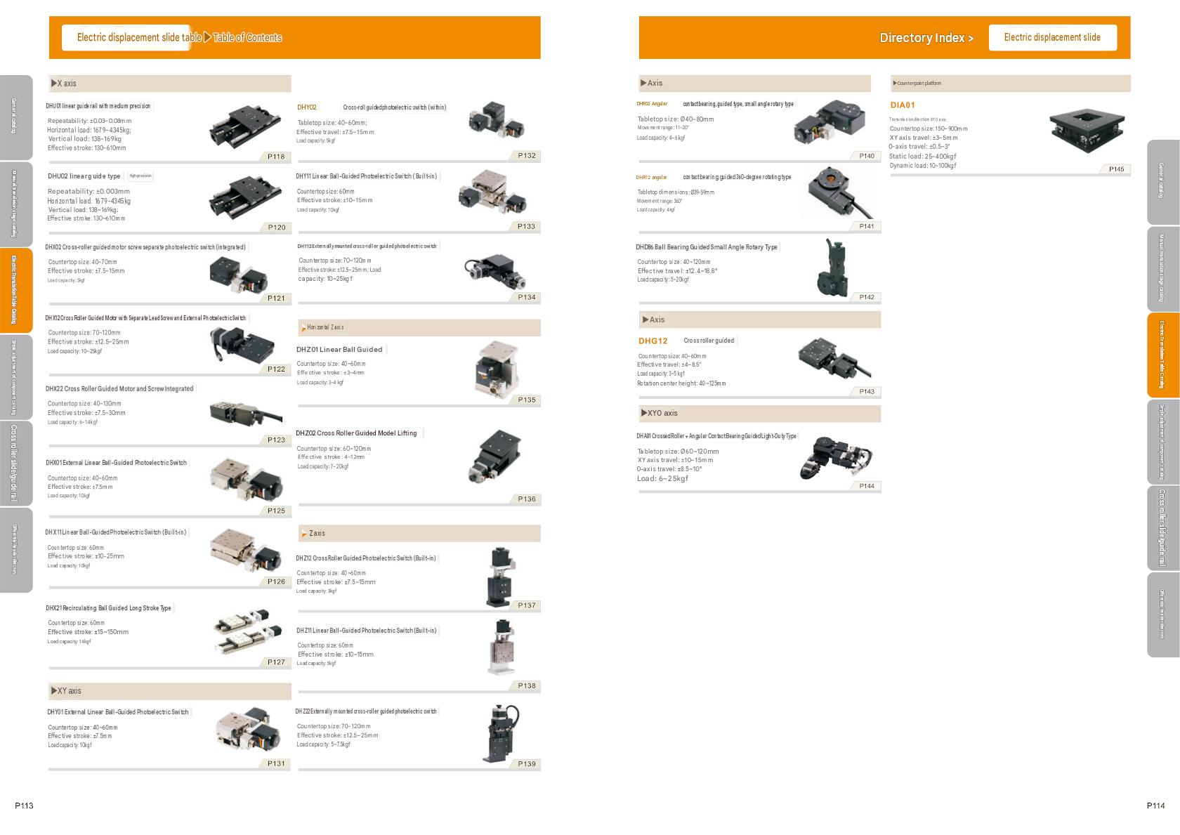
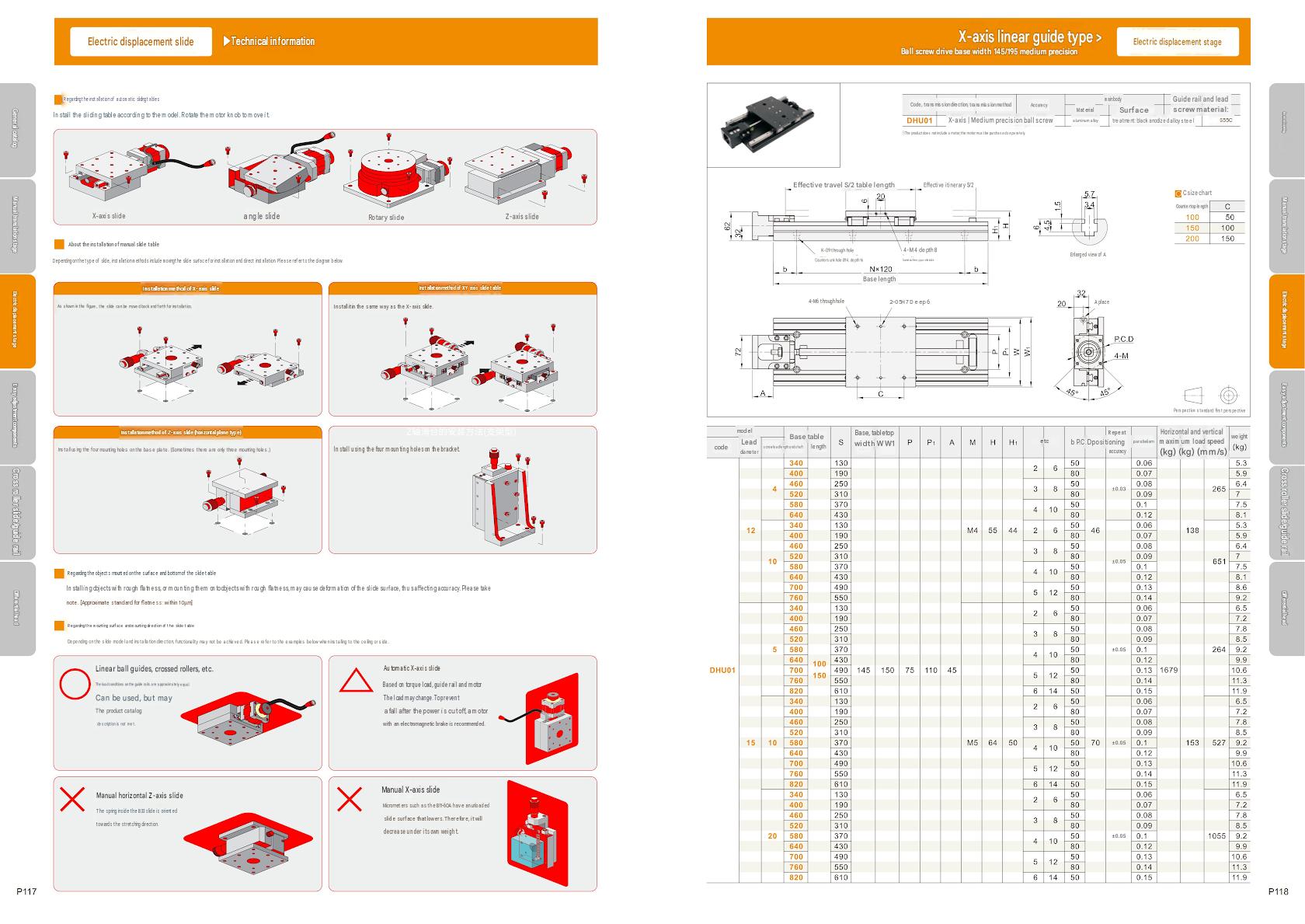
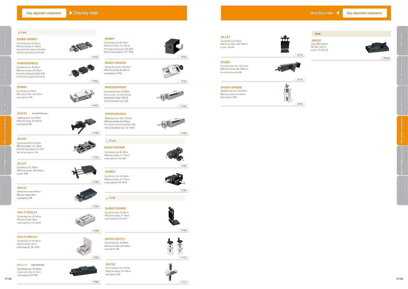
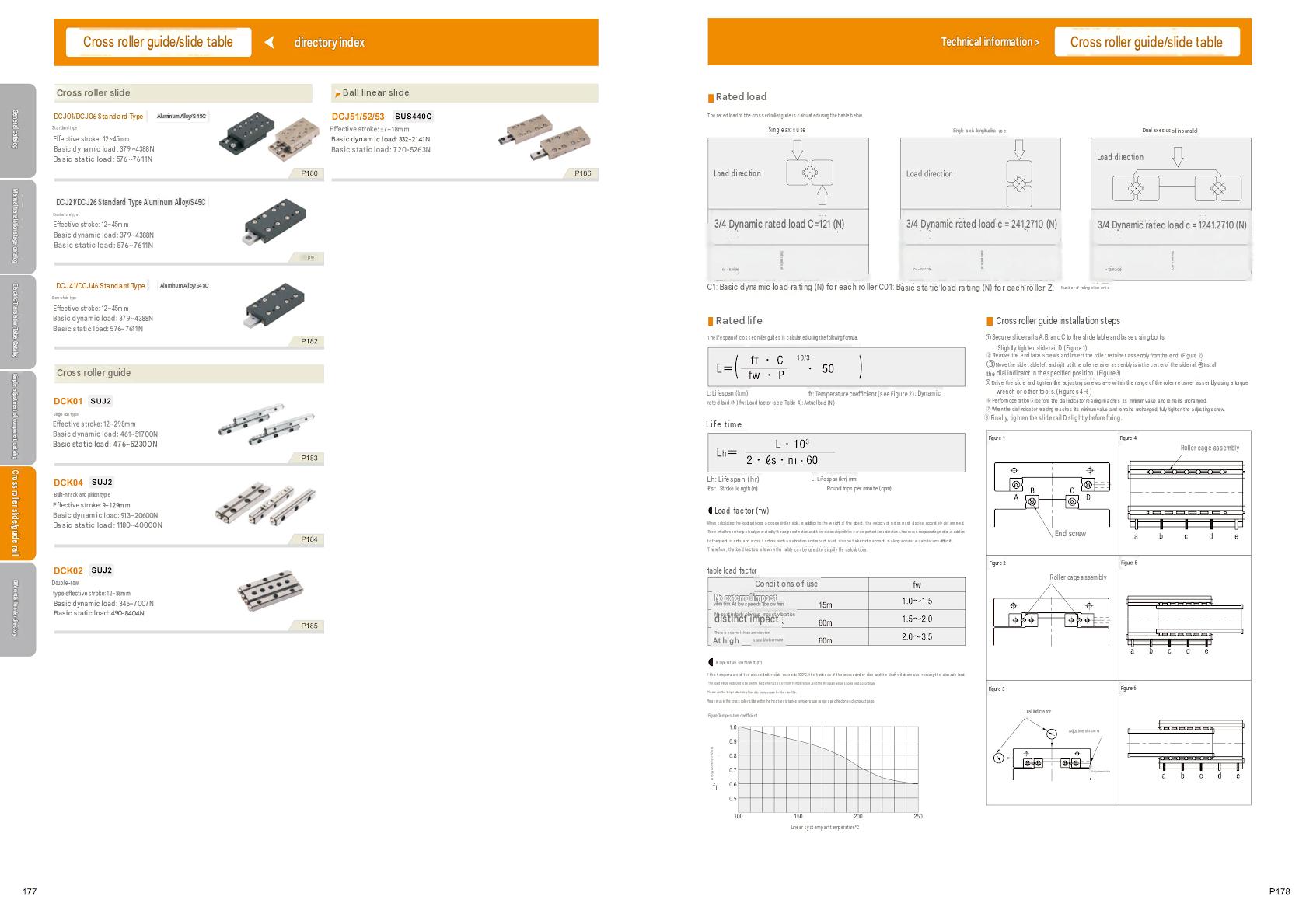
Frequently Asked Questions
Q1: What is a manual XYZ positioning stage?
A manual XYZ positioning stage is a precision mechanical device used to adjust the position of an object along the X, Y, and Z linear axes. It is commonly used for optical alignment, laboratory experiments, microscopy, measurement, and component positioning.
Q2: What is the advantage of a micrometer-driven positioning stage?
A micrometer head provides fine manual adjustment with quantitative displacement readings. It requires no motor, controller, or external power source, making it simple and convenient for laboratory and precision alignment applications.
Q3:What is the core difference between a 3-axis stage and a 6DOF motorized stage for fiber coupling?
A: A 3-axis platform only offers XYZ linear movement without angular adjustment, unable to correct fiber tilt and optical axis skew. The 6DOF motorized stage adds pitch, yaw and rotation compensation, which is indispensable for low-loss single-mode fiber coupling.
Q4: Can this stage work with fully automated fiber coupling production lines?
A: Yes. Equipped with automatic peak-search algorithms and closed-loop servo control, it supports uninterrupted batch operation and perfectly matches large-volume packaging of optical modules and photonic chips.
Q5: Will long-time continuous operation cause positioning drift?
A: The anti-backlash rigid locking structure and closed-loop motor control effectively suppress displacement drift, maintaining stable positioning accuracy during long-term running.
Q6: Can travel range, precision and mounting fixtures be customized?
A: Custom parameters, structural fixtures and control interfaces are available based on fiber specifications, chip dimensions and automation platform requirements.
Q7: Can the positioning stage be customized?
Yes. Different stage dimensions, travel ranges, micrometer configurations, mounting interfaces, and multi-axis combinations can be configured according to specific application requirements.
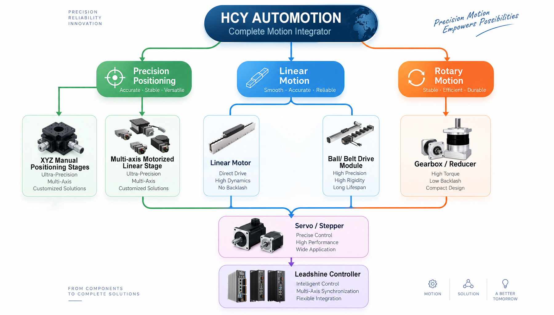
HCY Automation — Your Complete Motion Integrator
At HCY Automation, we go beyond individual motion components. We provide complete motion solutions covering motion control, motor drive, linear motion, positioning stages, and multi-axis systems,Flexible OEM Solutions
| Type |
Manual Linear Stage |
|---|---|
| Table Size(mm) |
40-130 |
| Horizontal Load Capacity(KG) |
1679-4345 |
| Positioning Repeatability(mm) |
±0.03 |
| Effective Stroke(mm) |
130-610 |