The Complete Engineering Guide to Phase Matching, Driver Integration, and Industrial Motion Optimization
Precision motion control underpins the reliability of modern automated systems. Within the landscape of precision positioning, stepper motors serve as the bedrock for multi-axis configurations, offering excellent holding torque, open-loop simplicity, and precise angular resolution without the immediate cost overhead of complex optical feedback systems.
Among these, compact NEMA frame units find critical applications across electronic manufacturing, scientific instruments, and custom automation. However, deploying a high-performance variant like the 14HS17-0604S—a specialized 4-wire 2 phase stepper motor—requires an exact understanding of its internal phase coils and electronic interface requirements. Missteps in your initial installation can lead to erratic behavior, thermal failure, or damaged silicon on your motor stepper driver boards.
This comprehensive guide delivers the definitive stepper motor 14hs17-0604s wiring diagram layout, technical specifications, driver calculations, and strategic integration insights for enterprise automation engineers. Whether you are scaling production lines or optimizing precision equipment, understanding these parameters ensures max system reliability. For industrial operations seeking to upgrade or source high-performance components, partnering with a proven technical manufacturer like HCY Automation ensures access to elite engineering support and robust motion hardware optimized for prolonged duty cycles.
1. Technical Analysis: The Anatomy and Specs of the 14HS17-0604S
The 14HS17-0604S belongs to the high-efficiency family of hybrid stepper motor architectures. It combines the design traits of a permanent magnet stepper motor with a variable reluctance rotor, allowing it to achieve minute step angles with excellent detent and holding torque properties.
Understanding NEMA Framework Dimensions
When dealing with standard automation footprints, understanding nema stepper motor sizes is vital for mechanical design. The “14” in NEMA 14 signifies that the motor faceplate measures approximately 1.4 inches square.
NEMA 8 stepper motor / nema 08 stepper motor / nema 11 stepper motor: Reserved for extremely space-constrained applications, such as medical fluid pumps or microscopic camera gimbals.
NEMA 14 stepper motor: Serves as the middle ground between micro-positioning and standard industrial frames, optimizing the torque-to-weight ratio.
NEMA 17 stepper motor / nema17 stepper motor: The absolute standard for light-duty automation, commercial 3D scanning, and desktop prototyping.
NEMA 23 stepper motor/ 23 nema stepper motor / nema23 stepper motor: Used for medium-duty machinery, material handling setups, and packaging equipment.
NEMA 34 stepper motor / 34 nema stepper motor / motor stepper nema 34: Built for heavy-duty industrial gantries, massive routing tables, and high-torque machinery.
NEMA 42 stepper motor: Designed for high-capacity industrial automation and heavy material handling.
Review the comprehensive physical footprint data across standard industrial configurations below:
NEMA Frame Size
Faceplate Dimensions (mm)
Typical Mounting Hole Pattern (mm)
Standard Applications
NEMA 8
20.0 x 20.0
16.0 x 16.0
Optical focus arrays, tiny stepper motors
NEMA 11
28.0 x 28.0
23.0 x 23.0
Miniature stepper motor fluid handling, laboratory pumps
NEMA 14
35.2 x 35.2
26.0 x 26.0
Mini stepper motor pick-and-place, specific medical devices
NEMA 17
42.3 x 42.3
31.0 x 31.0
Stepper motor 3d printer builds, light automated gantries
NEMA 23
56.4 x 56.4
47.1 x 47.1
Cnc stepper motor axes, 2 rail edge conveyor with stepper motor
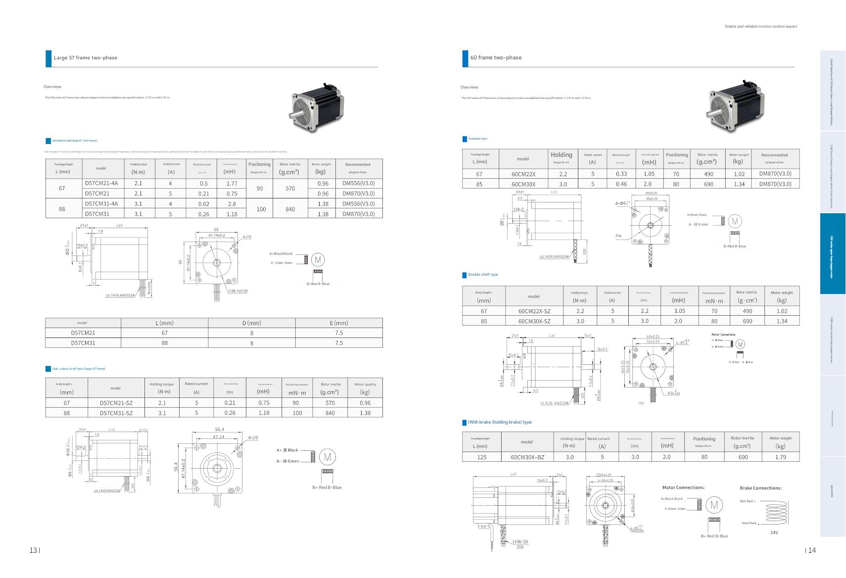
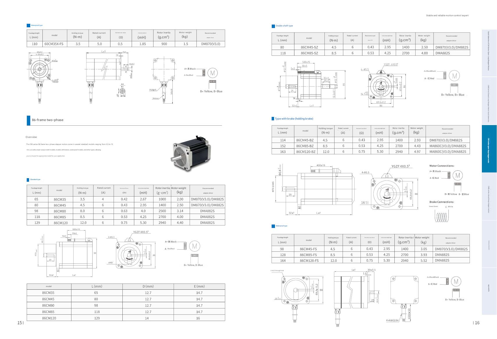
Looking closely at nema stepper motor dimensions, the 14HS17-0604S matches the NEMA 14 standard with a 35.2mm faceplate profile. However, its specific internal winding makes it distinct from standard catalog items, offering a rated current optimized at 0.6A per phase, which strikes a careful balance between high holding torque and low heat generation.
2. Stepper Motor 14HS17-0604S Wiring Diagram & Phase Grouping
Correctly interpreting your stepper motor wiring diagram is the most crucial step of hardware installation. The 14HS17-0604S is a bipolar motor stepper configuration containing two independent internal phase coils.
Unlike an older unipolar vs bipolar stepper motor comparison where unipolar motors used 5 or 6 wires with center taps to simplify driver circuits, modern premium automation relies on the 4-wire bipolar format. Bipolar coils utilize 100% of the copper windings during operation, ensuring a significantly higher stepper motor torque output relative to the motor’s total volume.
Identifying the Phase Pairs
To execute a flawless stepper motor wire diagram connection, you must correctly match the internal coils. While standard lead configurations typically use uniform color sets, batch shifts or localized supply chains can introduce variations.
The standard wire color configuration for the 14HS17-0604S is:
Phase A Winding: Red Lead (A+) and Blue Lead (A-)
Phase B Winding: Green Lead (B+) and Black Lead (B-)
Verification Techniques for Unknown Stepper Motor Wires
If your specific procurement batch lacks verified documentation, never guess your stepper motor wire colors. You can isolate the correct pairings in two ways:
The Multimeter Test: Switch your digital multimeter to resistance/continuity mode. Touch the leads across the different wires. If you measure a distinct low resistance (typically between 2 to 30 ohms depending on the specific nema 17 stepper motor datasheet or NEMA 14 specs), you have successfully mapped a complete coil phase. If the meter displays an open circuit (OL), you are measuring across two separate, insulated coils.
The Short-Circuit Resistance Trick: Twist two leads together by hand and try spinning the motor shaft. If the shaft suddenly becomes noticeably harder to turn, you have short-circuited a complete phase loop. If the rotation remains smooth, those two wires belong to opposite internal circuits.
Once identified, map these lines directly to your stepper motor connection diagram inputs on your industrial driver.
3. Industrial Driver Integration: A4988, DRV8825, and TB6600
A stepper motor with controller systems requires an intermediary driver to handle high-current switching based on low-voltage logic pulses. Selecting the correct stepper motor driver board or dedicated ic stepper motor driver dictates the speed, efficiency, and noise signature of your motion axis.
Driver Comparison Matrix
When selecting an industrial architecture for the 14HS17-0604S, three primary driver architectures dominate the market. The table below outlines how these options compare:
Driver IC / Module
Max Peak Current
Microstep Resolution
Preferred Use Case Scenario
Stepper motor driver a4988
2.0A
Up to 1/16
Cost-sensitive electronics, light automation
Drv8825 stepper motor driver
2.2A
Up to 1/32
Higher voltage supply loops, quiet operation
Tb6600 stepper motor driver
4.0A
Up to 1/32
Enclosed industrial panels, cnc stepper motor designs
Pin Map Connections for Common Drivers
Connecting the 4-wire configuration to an external stepper motor driver controller follows a precise sequence across different hardware layouts:
[ 14HS17-0604S Motor Leads ]
  Red    -->  Phase A+
  Blue   -->  Phase A-
  Green  -->  Phase B+
  Black  -->  Phase B-
                 |
                 v
[ Driver Block Terminal Interface ]
  A4988 Module:    Connect to pins labeled 1A, 1B (Phase A) and 2A, 2B (Phase B)
  DRV8825 Module:  Connect to pins labeled A1, A2 (Phase A) and B1, B2 (Phase B)
  TB6600 Enclosed: Connect directly to screw terminals A+, A-, B+, B-
4. Advanced Control Frameworks: Arduino, CircuitPython, and Firmware Inversion
Driving the logic side of your system requires clean software execution. Depending on your control platform, you can orchestrate multi-axis movements using varied software layers.
For embedded systems developers utilizing modern Adafruit boards or RP2040 silicon, you can easily control bipolar stepper motors circuitpython scripts using dedicated hardware timer libraries.
Resolving Inverted Rotation
If your axis moves backward during initial testing, don’t waste time pulling apart your physical wiring terminals. Instead, apply a quick software fix:
In Klipper Firmware: Find your configuration file and locate the specific axis block. Add or remove an exclamation point to the direction pin setting
In Marlin Firmware: Navigate to Configuration.h and invert the boolean flag for your targeted axis
5. Modern Industrial Application Trends & Motion Systems
Precision stepper technologies have expanded far beyond vintage manufacturing lines, anchoring themselves across highly specialized modern applications.
1. Advanced Additive Manufacturing
In high-temperature setups, a stepper motor in 3d printer setups encounters extreme ambient conditions. The stepper motor 3d printer axis demands tight dimensional stability. Compact NEMA 14 and stepper motor nema 17 units act as direct-drive extruder motors, where light weight directly reduces print-head inertia, completely eliminating surface ghosting and ringing artifacts at high printing speeds.
2. Intelligent Conveyors and Intralogistics
In high-speed sorting and electronics production lines, a 2 rail edge conveyor with stepper motor drive provides precise indexing capabilities that standard AC motors cannot achieve without expensive mechanical braking setups. These configurations allow precise pick-and-place indexing without complex mechanical stops.
3. Specialty Mechanical Engineering
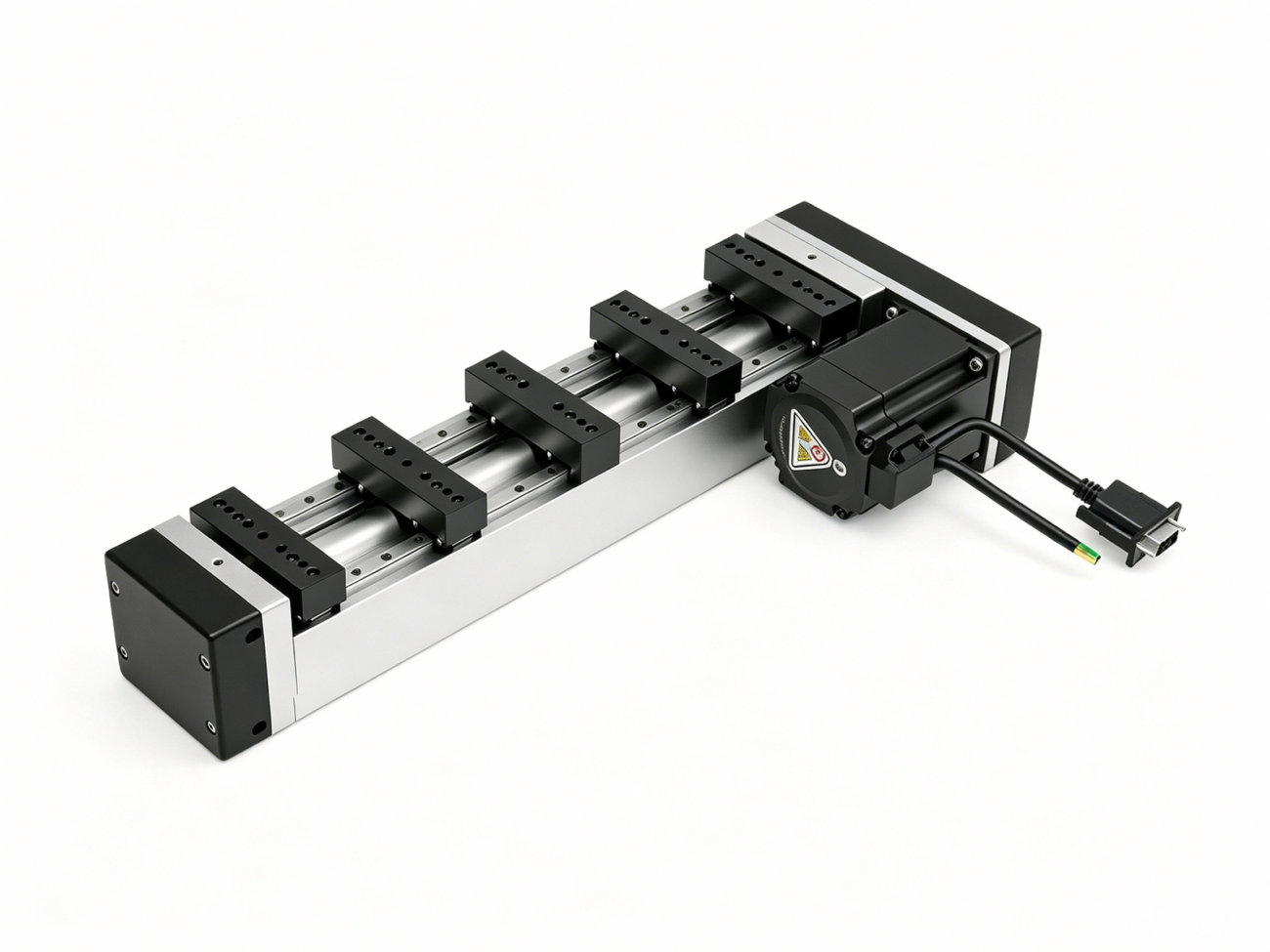
From heavy industrial indexing wheels using a specialized stepper motor for lazy susan assembly tables to high-torque geared stepper motor units driving fluid valves in a stepper motor water control array, small-profile steppers deliver repeatable holding torque. When paired with a lead screw stepper motor or stepper motor and lead screw assembly, they form an integrated stepper motor linear actuator or linear stepper motor that removes the backlash issues common to external couplings.
6. Comprehensive Troubleshooting Guide: Squealing, Vibration, and Noise
Even with a proper stepper motor wiring diagram setup, unexpected mechanical or electrical issues can pop up during commissioning.
Diagnosing “Why is my stepper motor making a squealing noise?”
When engineers ask why is my stepper motor making a squealing noise, the issue is almost always electrical rather than mechanical. High-pitched squealing occurs when the stepper motor driver ic or stepper motor driver chip feeds current through the coils while the motor is stationary, creating high-frequency chopper switching noise.
To resolve this issue:
Enable automated idle-current reduction settings in your stepper motor controllers to drop current down to 30% when the motor is holding still.
Increase your microstepping resolution on your stepper motor driver board to smooth out the phase currents.
Tune the chopper frequency voltage via your firmware configuration to push the acoustic resonance out of the audible human spectrum.
Resolving Phase Faults: “Motor vibrates but doesn’t turn”
If your stepper motor vibrates but doesn’t turn, your system is experiencing an incomplete phase cycle. This symptom points to one of three common causes:
Broken Internal Connection: One of your stepper motor wires has come loose from its terminal screw, dropping the system down to single-coil excitation.
Mismatched Phase Pairing: Your stepper motor wire diagram layout is incorrect, pairing one wire from Coil A with another from Coil B on the same output terminal.
Insufficient Current Delivery: The stepper motor power supply or local driver potentiometer is set too low, failing to provide enough electrical current to overcome the rotor’s static detent torque.
7. Deep Technology Comparison: Stepper vs. Servo Systems
For large-scale industrial projects, choosing between stepper motors vs servo motors is a foundational engineering decision that dictates your overall control topology and bill-of-materials cost.
Stepper vs Servo Motor Performance Profiles
Understanding the core difference between servo and stepper motor performance requires looking at their underlying feedback design. Standard nema stepper motors are traditionally open-loop systems that move to designated step positions without verifying if the rotor actually reached its destination. Conversely, a servo motors vs stepper motors comparison highlights that servo systems use continuous closed-loop feedback via a built-in optical or magnetic encoder.
Review the core operational trade-offs below:
  FEATURE               STEPPER MOTOR                      SERVO MOTOR
  ----------------------------------------------------------------------------------
  Feedback Loop         Typically Open-Loop                Continuous Closed-Loop
  Torque Profile        Max Torque at Low Speed            Flat Torque across High Speeds
  Cost Footprint        Highly Cost-Effective              Premium Investment Cost
  Tuning Complexity     Plug-and-Play Integration           Demands Complex PID Tuning
For applications requiring the rock-solid reliability of a servo system without the extreme cost overhead, engineers turn to the closed-loop stepper motor or a stepper motor with encoder configuration. By adding a stepper motor encoder to a traditional frame, your closed-loop stepper motor control system can instantly detect missed steps, eliminate positional drift, and drastically reduce overall stepper motor power requirements by dynamically adjusting current based on the real-time physical load.
Leverage Precision Engineering with HCY Automation
Achieving reliable precision on the factory floor requires more than just following a wiring diagram—it demands high-quality, dependable hardware. HCY Automation specializes in manufacturing premium industrial motion control equipment, including high torque stepper motor units, custom stepper motor kit packages, and robust stepper motor controllers engineered for continuous industrial operations.
Why Leading Industrial Operations Choose HCY Automation:
Strict Structural Reliability: Every high torque stepper motors unit from HCY Automation is built using premium laminated steel and heat-resistant copper coils, preventing common insulation failures and keeping your lines running smoothly.
Expert Application Engineering: Our technical support team assists you through every phase of implementation, from initial stepper motor power supply calculations to advanced multi-axis tuning.
Diverse Product Portfolio: We offer a complete range of motion solutions, from ultra-precise micro stepper motor models for medical devices to massive nema 34 stepper motor setups for industrial CNC machinery.
Don’t let unexpected positioning errors or motor failures slow down your production lines. Upgrade your automated systems with robust, high-performance hardware designed for modern manufacturing. Contact the application engineering team at HCY Automation today to request custom product datasheets, secure volume quotes, or find the ideal motion solution for your next project.
HCY Automation delivers integrated solutions across motion control, linear motion, robotics, machine vision, pneumatic systems, and precision gearboxes to help global manufacturers build smarter, faster, and more reliable production lines. Our engineering team helps you select and integrate the right motion control, robotics, and automation components for your specific application.