6‑Axis Alignment Stage: Why 6‑DOF Is Critical for Fiber‑to‑Chip Coupling
6‑Axis Alignment Stage: How 6‑DOF XYZ + Angular Tuning Solves Modern Fiber‑Coupling Challenges
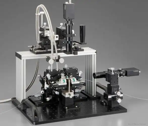
Traditional 3‑axis translation stages cannot compensate angular tilt, yaw or roll errors in fiber‑to‑chip alignment. A 6‑axis (6‑DOF) alignment stage delivers X‑Y‑Z linear translation plus θX, θY, θZ angular deflection, minimizing insertion loss, shortening debug cycles and improving repeatability for silicon photonics, CPO, TOSA/ROSA, PLC and AWG device manufacturing. Manual and automated coupling systems rely on six‑degree‑of‑freedom positioning to hit low‑loss optical coupling targets.
What Is 6‑DOF Alignment for Fiber‑Optic Coupling?
Fiber‑to‑chip coupling demands ultra‑precise spatial matching between optical fibers and photonic integrated circuits (PICs), laser diodes, detectors or waveguide arrays. Even nanometer‑level positional shift or tiny angular misalignment will raise insertion loss and degrade device performance, especially for single‑mode fiber applications with tiny mode‑field diameters.
Six degrees of freedom (6‑DOF) breaks down into:
XYZ: Three linear translation axes — adjust lateral, longitudinal and vertical spatial position
θX, θY, θZ: Three angular deflection axes — compensate tilt, pitch, yaw and rotational misalignment of fiber end‑faces
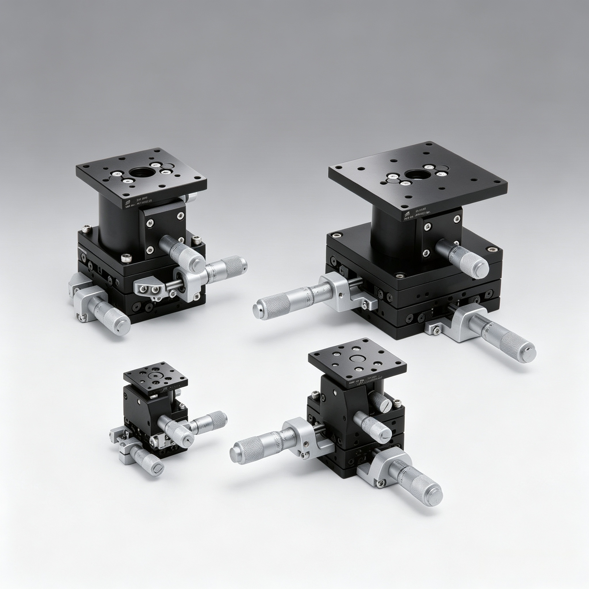
A 6‑axis alignment stage integrates all six tuning capabilities inside one mechanical unit. Operators can simultaneously fine‑tune both position and angle, rather than adjusting translation and tilt in separate hardware assemblies. This multi‑dimensional control forms the mechanical foundation for high‑yield active optical alignment in modern optoelectronics R&D and mass production.
Why 3‑Axis XYZ Stages Fall Short for Photonics Packaging
Many optical labs start coupling work with simple XYZ three‑axis translation stages. These platforms handle linear movement well, yet they carry hard limitations for today’s high‑speed photonic devices.
Core Pain Points of Pure 3‑Axis Positioning
No angular error compensation: Fiber end‑face tilt, mounting skew or optical‑axis misalignment cannot be corrected by translation only. You can move the fiber in X‑Y‑Z, but you cannot fix tilted beam incidence against chip waveguides.
Higher coupling loss: Even perfect XYZ positioning still suffers extra insertion loss when angle offset exists, directly lowering maximum achievable coupling efficiency.
Long trial‑and‑error debugging: Engineers spend excessive time re‑mounting fixtures to manually adjust tilt, slowing down R&D iteration.
Poor repeatability after locking: Fixture re‑mounting introduces new mechanical deviations; test‑to‑test consistency drops.
Not fit for CPO & silicon photonics requirements: Co‑packaged optics and multi‑channel fiber‑array coupling are extremely sensitive to angular deviation, making simple 3‑axis hardware insufficient for production‑grade active alignment.
For simple low‑precision experiments, 3‑axis stages remain acceptable. But for 400G / 800G transceivers, PIC validation, TOSA‑ROSA assembly and AWG testing, position‑and‑angle co‑tuning becomes non‑negotiable.
How 6‑Axis Alignment Stages Improve Fiber‑Chip Coupling Performance?
A well‑engineered 6‑DOF alignment stage synchronizes XYZ translation and θX‑θY‑θZ angular deflection. It addresses the above pain points through mechanical‑level multi‑dimensional fine‑tuning.
Major Technical Benefits
✅ Compensate both positional and angular offset: Correct fiber tilt, rotational skew and beam incidence angle without re‑fixturing parts.
✅ Lower insertion loss: Achieve near‑ideal optical‑axis matching between fiber and target component.
✅ Stable locking performance: Minimize position drift after completing alignment and mechanical lock‑down; control backlash to preserve alignment status.
✅ Superior repeatability: Consistent results across repeated coupling cycles, critical for device characterization and production quality control.
✅ Flexible for diverse devices: Works for single fiber, lensed fiber, multi‑channel fiber‑arrays, edge‑coupling and grating‑coupling setups.
Note: Performance depends on mechanical resolution, anti‑backlash design, locking rigidity and fixture compatibility. Not all six‑axis stages deliver equal stability after tightening locks.
Real‑World Industrial Applications of 6‑DOF Alignment Stages
6‑axis alignment stages are widely deployed across telecom, datacom and photonic R&D labs. Typical scenarios include:
Silicon photonics & PIC testing: Fiber‑array to waveguide chip alignment, edge coupling and grating coupling validation
Whether you run small‑batch R&D validation or prepare automated production workflows, 6‑DOF positioning becomes a shared requirement across these fast‑growing market segments.
Integration Into Automated Active‑Alignment Production Lines
Beyond manual laboratory operation, modern fiber‑coupling manufacturing moves toward full automation. A 6‑axis alignment stage acts as the motion core within end‑to‑end process workflows.
Typical integrated workflow:
Vision positioning locates fiber and chip reference markers
6‑axis stage performs coarse positioning
Optical‑power meter provides real‑time signal feedback
Multi‑DOF fine‑tuning searches for maximum optical‑power peak
Auto‑dispensing applies adhesive
UV‑LED curing locks fiber position while maintaining aligned status
Process metrology confirms final coupling‑loss performance before next station
When paired with vision systems, power‑sensing instruments and curing equipment, 6‑DOF hardware reduces human intervention, improves batch‑to‑batch consistency and shortens production cycle time for optoelectronic assemblies.
Field Case Study: Solving Poor Repeatability & Long Tuning Time
A photonics R&D company previously relied on stacked 3‑axis stages for fiber‑chip coupling. Their workflow suffered obvious bottlenecks:
Insufficient angular compensation capability
Extremely long manual debugging time
Unstable repeatability between separate test runs
Inconsistent measured coupling‑efficiency data
After deploying a high‑performance 6‑axis alignment stage supporting full XYZ‑θX‑θY‑θZ adjustment:
“With the six‑axis stage, fiber position and angular tuning become far more flexible. We rapidly locate the optimal coupling peak. Repeatability across multiple debugging cycles improves significantly, bringing tangible gains to our R&D throughput.” — R&D Manager, optoelectronic enterprise.
Engineers could simultaneously tune position and angles, cutting setup overhead and stabilizing final optical performance for their photonic‑device prototypes.
FAQ: 6‑Axis Alignment Stage for Photonics Engineers
What is the difference between 3‑DOF and 6‑DOF for fiber coupling?
3‑DOF only offers X‑Y‑Z linear translation with no angular adjustment. 6‑DOF adds θX, θY, θZ angular deflection for tilt and rotation compensation. 6‑axis hardware fixes optical‑axis skew that pure translation cannot resolve.
Do I need a motorized 6‑axis stage or manual version?
Manual 6‑axis alignment stages suit laboratory R&D and low‑volume prototyping. Motorized 6‑DOF stages fit automated active‑alignment production lines requiring software‑controlled peak‑search algorithms.
Can a 6‑axis alignment stage work for fiber‑array coupling in silicon photonics?
Yes. 6‑DOF positioning compensates both positional offset and angular skew across multi‑channel fiber‑arrays, which is essential for silicon‑photonics and CPO prototyping.
Will locking the stage cause alignment drift after peak coupling?
It depends on mechanical design. High‑quality 6‑axis stages adopt anti‑backlash rigid locking structures to minimize position shift during locking; low‑cost units may introduce noticeable drift after tightening.
Can you customize fixtures for special fiber or PIC form‑factors?
Yes. Custom fixture adaptation is common. Suppliers can tailor mounting interfaces for lensed fiber, fiber‑arrays, special chip carriers and automation‑platform integration requirements.
Key Takeaways
Tiny angular misalignment creates large insertion loss for single‑mode fiber coupling; pure XYZ 3‑axis stages cannot compensate tilt or rotation errors.
6‑axis (6‑DOF) alignment stages combine XYZ translation and θX‑θY‑θZ angular deflection to achieve complete spatial‑attitude control for fiber‑to‑chip alignment.
6‑DOF hardware cuts debugging time, improves repeatability and stabilizes coupling efficiency for silicon photonics, CPO, optical‑module packaging and passive‑component testing.
Both manual lab‑grade and automation‑ready motorized versions exist; mechanical rigidity and locking stability heavily determine real‑world performance.
6‑axis stages can integrate with vision, power‑meters, dispensing and UV‑curing equipment to build complete automated active‑alignment workflows.
Get Your Custom 6‑Axis Alignment Solution
Whether you require manual laboratory prototypes or automation‑ready 6‑DOF hardware for photonics manufacturing, selecting the correct alignment stage directly impacts your coupling yield and R&D efficiency.
HCY Automation delivers complete 6‑axis alignment‑stage and fiber‑coupling‑system solutions. We support sample evaluation, fixture customization and full process‑validation technical support for silicon photonics, CPO, optical‑transceiver and PIC‑packaging projects.
👉 Contact HCY Automation today for datasheets, sample testing or your tailored quotation.
HCY Automation delivers integrated solutions across motion control, linear motion, robotics, machine vision, pneumatic systems, and precision gearboxes to help global manufacturers build smarter, faster, and more reliable production lines. Our engineering team helps you select and integrate the right motion control, robotics, and automation components for your specific application.