How to Choose a Linear Motor: A Practical Guide for Engineers and Machine Designers
Learn how to choose a linear motor based on force, speed, acceleration, stroke, precision, thermal performance, feedback, and application requirements. Complete Selection Guide
When a machine needs fast, precise, and highly responsive linear motion, alinear motor can be an attractive alternative to traditional mechanical transmission systems such as ball screws, belts, racks, and gearboxes.
But choosing a linear motor is not as simple as comparing maximum thrust or maximum speed on a datasheet.
A motor that looks powerful enough on paper may overheat during continuous operation. A motor with an extremely high-resolution encoder may still fail to achieve the required machine accuracy. An iron-core motor may provide excellent thrust but introduce magnetic attraction and force ripple that affect the mechanical design.
So, how do you choose the right linear motor?
The answer starts with the application—not the motor catalog.
This guide explains a practical engineering approach to linear motor selection, including force calculation, speed and acceleration, continuous versus peak force, motor type, encoder selection, thermal management, mechanical compatibility, and final validation.
What Should You Consider When Choosing a Linear Motor?
A reliable linear motor selection process should evaluate at least these eight factors:
Required force
Maximum speed
Acceleration and motion profile
Stroke and mechanical configuration
Positioning accuracy and repeatability
Thermal performance
Feedback and servo drive compatibility
Operating environment and service life
The important point is that these factors are interconnected.
For example, increasing acceleration increases required thrust. Increasing continuous force increases heat generation. Increasing speed may make back EMF and drive voltage more important. Choosing an iron-core motor may increase force density but also introduce magnetic attraction that must be handled by the guide system.
That is why linear motor sizing should be performed as a complete motion-system calculation, rather than a simple product comparison. KKollmorgen+1
Step 1: Start With the Application, Not the Motor
Before looking at any linear motor model, define what the machine actually needs to do.
At minimum, collect:
Application Parameter
Typical Unit
Moving mass
kg
Payload
kg
Stroke
mm
Maximum speed
m/s
Acceleration
m/s²
Deceleration
m/s²
Cycle time
s
External process force
N
Installation orientation
Horizontal / Vertical / Inclined
Positioning accuracy
μm
Repeatability
μm
Ambient temperature
°C
Duty cycle
%
This information creates the foundation for motor sizing.
A useful rule is:
Do not ask “Which linear motor is the strongest?” Ask “Which linear motor can satisfy my complete motion profile?”
Step 2: Calculate the Required Linear Motor Force
The first major sizing question is how much force the motor must generate.
For a basic horizontal axis:
Ftotal = ma + Ffriction + Fprocess
Where:
Ftotal = required motor force
m = total moving mass
a = acceleration
Ffriction = guide and mechanical resistance
Fprocess = external process force
For a vertical axis, gravity must also be included:
Ftotal = ma + mg + Ffriction + Fprocess
This distinction is extremely important.
A horizontal inspection stage and a vertical lifting stage may have the same payload and acceleration but require very different motor forces.
A Simple Linear Motor Sizing Example
Suppose an axis has:
Moving mass: 15 kg
Acceleration: 8 m/s²
Mechanical resistance: 15 N
Process force: 25 N
Acceleration force is:
Facc = 15 × 8 = 120 N
Total estimated force:
Ftotal = 120 + 15 + 25 = 160 N
This 160 N is the approximate force requirement for that motion segment.
The actual motor selection should then include appropriate engineering margin and account for the complete duty cycle.
Also remember that the moving mass should include more than the payload.
It may include:
Workpiece
Fixture
Stage
Moving motor component
Cable carrier
Encoder components
Other moving assemblies
For high-acceleration machines, overlooking motor moving mass can produce an inaccurate sizing result.
Step 3: Understand Peak Force vs. Continuous Force
This is probably the most important concept in linear motor selection.
Linear motors commonly have both a peak force rating and a continuous force rating.
These ratings serve different purposes.
Peak Force
Peak force is associated with short-duration dynamic events such as:
Rapid acceleration
Emergency deceleration
Fast positioning
Short process-force peaks
High-frequency trajectory changes
Continuous Force
Continuous force is related to the amount of force the motor can sustain within its specified thermal limits.
The difference can be substantial.
For example, current product data from major linear motor manufacturers shows that a motor family may have continuous force ratings far below its peak force ratings. This is why selecting a motor based only on its headline peak thrust can lead to thermal problems in real production. KKollmorgen+1
The key rule:
Peak force answers “Can the motor perform the move?” Continuous force answers “Can the motor keep doing it without exceeding its thermal limits?”
You need both answers.
Step 4: Calculate RMS Force for Real Production Cycles
Industrial equipment rarely runs at maximum force continuously.
Each section may have a different force requirement.
For a simplified duty cycle:
Fᵣₘₛ = √[(F₁²t₁ + F₂²t₂ + F₃²t₃ + …)/T]
Where:
F₁, F₂, F₃ = force during each motion segment
t₁, t₂, t₃ = duration of each segment
T = complete cycle time
The calculated RMS force should then be compared with the motor’s continuous capability under the actual cooling and installation conditions.
This is particularly important for:
High-speed pick-and-place
Packaging machinery
Semiconductor equipment
Repetitive inspection
Battery manufacturing
High-frequency reciprocating stages
A motor can survive a short peak-force event but still fail if the average thermal load over thousands of cycles is too high.
Step 5: Determine the Required Speed
The next question is:
How fast does the axis actually need to move?
Do not simply use the highest possible speed from the motor catalog.
Determine the required:
Maximum velocity
Average velocity
Acceleration
Deceleration
Travel distance
Cycle time
For example, an axis that travels 500 mm at 2 m/s has very different requirements from an axis that travels the same distance at 2 m/s but must reach that speed within 50 ms.
The second application requires much higher acceleration and therefore much higher peak force.
Step 6: Understand the Relationship Between Speed, Voltage and Back EMF
High-speed linear motor applications need another parameter: back EMF.
As linear motor speed increases, back EMF also increases.
Eventually, the available drive voltage becomes a limiting factor.
This means:
A motor may have sufficient thrust capability but still be unable to reach the required speed with a particular drive and DC bus voltage.
Therefore, high-speed selection should evaluate:
Motor back EMF constant
Drive bus voltage
Maximum motor current
Winding configuration
Required speed
Drive voltage margin
This is particularly relevant to high-speed machine tools, semiconductor equipment, inspection systems, and industrial automation.
Recent high-voltage linear motor developments also demonstrate why supply voltage becomes important when applications require high force at high speed. KKollmorgen
Step 7: Choose Between Iron-Core and Ironless Linear Motors
One of the biggest decisions in linear motor design is the motor architecture.
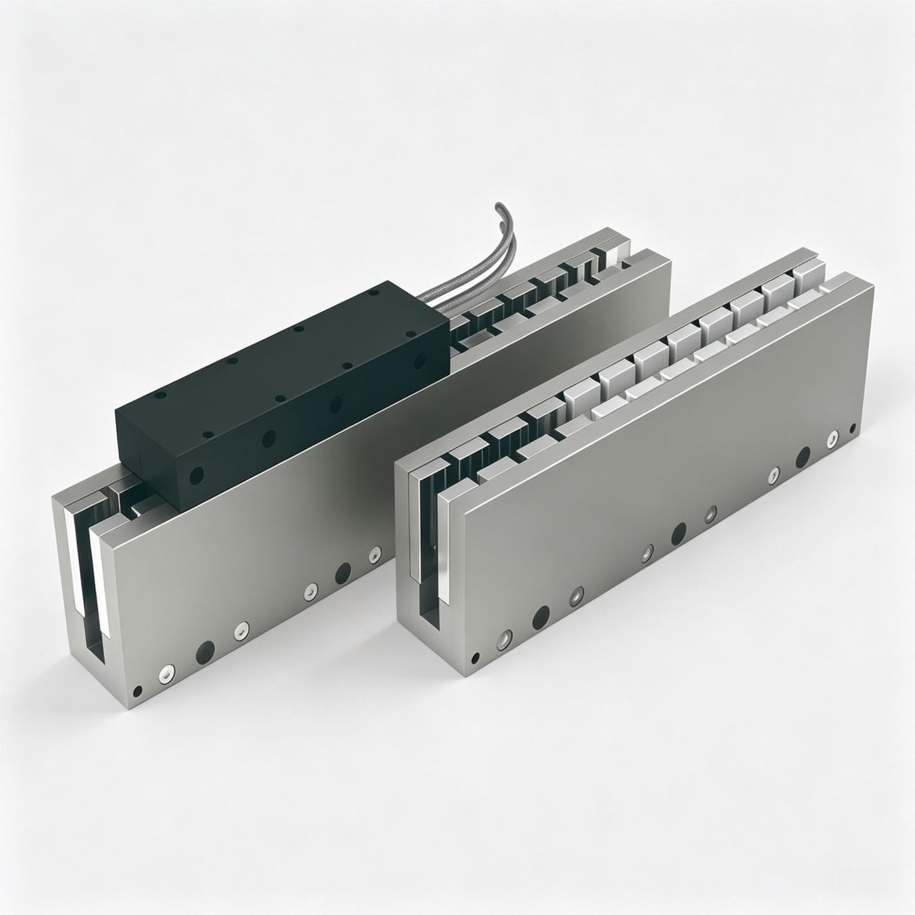
Iron-core motors use an iron structure in the moving or stationary magnetic circuit to increase magnetic flux concentration.
Advantages
High force density
Strong continuous thrust capability
Suitable for heavier loads
Good choice where compact force generation is important
Considerations
Magnetic attraction force
Potential cogging/force ripple
Greater mechanical guide loading
Greater sensitivity to some precision-motion requirements
Iron-core designs are commonly attractive when high thrust and force density are more important than ultra-smooth low-speed motion. KKollmorgen+1
Ironless Linear Motors
Ironless motors eliminate the iron core from the moving coil structure.
Advantages
Low moving mass
Smooth motion
Very low cogging characteristics
Excellent acceleration potential
Attractive for precision positioning
Considerations
Lower force density in many designs
May require more installation space for equivalent thrust
Mechanical design must still account for the magnetic track and guide system
Ironless designs are often attractive for precision inspection, semiconductor equipment, optical systems, and high-speed lightweight stages. KKollmorgen
Iron-Core vs. Ironless Linear Motor: Quick Comparison
Requirement
Iron-Core
Ironless
Force density
High
Moderate
Heavy loads
Excellent
Application dependent
Low moving mass
Moderate
Excellent
Smooth motion
Good
Excellent
Cogging
Possible
Very low/zero depending on design
Magnetic attraction
Important consideration
Generally much lower
High acceleration
Good
Excellent for lightweight movers
Precision applications
Good with proper design
Very attractive
Guide loading
Higher consideration
Lower
The best choice should be based on the actual mechanical and motion requirements rather than the motor category alone.
Step 8: Check Magnetic Attraction and Linear Guide Loading
This issue is frequently overlooked during early design.
Iron-core linear motors can generate significant normal magnetic attraction between the coil assembly and magnet track.
That force does not directly move the load forward—but it can significantly increase the load experienced by the linear guide system.
Therefore, when selecting an iron-core motor, also verify:
Guide block load rating
Static load
Dynamic load
Moment load
Bearing preload
Friction
Expected service life
This creates an important design relationship:
Linear Motor Selection ↔ Linear Guide Selection
The two should not be treated as independent components.
Step 9: Select the Right Linear Encoder
The encoder is the “eyes” of a closed-loop linear motion system.
Common technologies include:
Optical linear encoders
Magnetic linear encoders
Inductive position sensors
Incremental encoders
Absolute linear encoders
For demanding precision applications, optical encoders are often selected because of their high resolution and accuracy potential.
But there is a critical difference between encoder resolution and machine accuracy.
Resolution
How finely the feedback system can detect position changes.
Accuracy
How closely the measured or actual position corresponds to the true physical position.
Repeatability
How consistently the machine returns to the same position.
A high-resolution encoder cannot compensate for:
Poor guide accuracy
Structural deformation
Thermal expansion
Vibration
Motor force ripple
Poor servo tuning
Encoder installation errors
Therefore:
Never select an encoder based on resolution alone.
The entire error budget must be considered.
Step 10: Define the Required Positioning Performance
Before choosing a feedback system, answer three questions:
1. How accurate must the machine be?
For example:
±10 μm
±5 μm
±1 μm
Sub-micron
2. How repeatable must the machine be?
A machine may need excellent repeatability even when its absolute accuracy requirements are moderate.
3. How fast must the axis settle?
A precision machine may achieve excellent final positioning but still fail the production requirement if its settling time is too long.
Therefore, precision specifications should include more than a single number.
Consider:
Positioning accuracy
Repeatability
Resolution
Following error
Settling time
Straightness
Thermal drift
Vibration
Step 11: Evaluate Thermal Performance
Heat is one of the biggest practical limitations of linear motors.
Electrical losses generate heat inside the windings, and the ability to remove that heat determines the motor’s continuous operating capability.
Important parameters include:
Winding resistance
Continuous current
RMS current
Thermal resistance
Ambient temperature
Cooling method
Motor mounting structure
Maximum winding temperature
For example, published motor data may specify continuous force at a particular maximum coil temperature. That rating should not be copied blindly into a machine operating under completely different thermal conditions. KKollmorgen
Natural Cooling or Water Cooling?
For high-duty-cycle machines, cooling can become a major design decision.
Natural or Passive Cooling
Advantages:
Simpler
Lower system cost
Less maintenance
No water circuit required
Suitable for many moderate-duty applications.
Liquid Cooling
Advantages:
Higher heat-removal capability
Higher continuous force potential
Better suitability for compact high-power designs
Potential disadvantages:
Additional plumbing
Pump or chiller requirements
More system components
Leak-management considerations
The best cooling strategy depends on the required continuous force and machine environment.
Step 12: Consider the Mechanical Structure
A linear motor does not operate in isolation.
Its performance depends heavily on the machine structure.
Check:
Mounting flatness
Parallelism
Structural stiffness
Guide alignment
Motor air gap
Magnet-track straightness
Fastener design
Cable management
The motor manufacturer’s specified mechanical tolerances should always be followed.
Do not assume that a generic air-gap value applies to every linear motor. The correct gap depends on the specific motor architecture and manufacturer specification.
Step 13: Check the Servo Drive Before Finalizing the Motor
A motor and drive must be electrically and dynamically compatible.
Verify:
Peak current
Continuous current
Bus voltage
Motor resistance
Motor inductance
Back EMF
Force constant
Feedback interface
Commutation method
Regeneration capability
Servo bandwidth
For example, if the motor requires a higher peak current than the drive can provide, the theoretical peak force will not be achievable.
Similarly, a high-speed motor may be limited by drive voltage even when its mechanical design allows a higher speed.
Step 14: Consider the Operating Environment
Where will the linear motor operate?
This question can eliminate certain motor designs before detailed sizing even begins.
Consider:
Ambient temperature
Humidity
Dust
Oil
Coolant
Metal chips
Cleanroom requirements
Vacuum
Corrosive chemicals
IP protection
Cable-chain environment
For semiconductor and electronics manufacturing, contamination and thermal stability may be major considerations.
For machine tools, coolant, chips, vibration, and thermal drift may dominate.
For factory automation, dust, cycle time, and maintenance requirements may be more important.
Step 15: Match the Motor to the Application
Different applications prioritize different characteristics.
Semiconductor and Precision Equipment
Prioritize:
Low force ripple
High positioning accuracy
High repeatability
Low vibration
Thermal stability
High-resolution feedback
Ironless linear motors are often attractive for these requirements because of their smooth motion characteristics. KKollmorgen
Machine Tools
Prioritize:
High continuous force
High dynamic stiffness
High acceleration
Thermal management
Structural rigidity
High-speed operation
Iron-core solutions can be attractive where high force density is required.
Pick-and-Place Automation
Prioritize:
Acceleration
Cycle time
Moving mass
Peak force
Servo response
High-Speed Inspection
Prioritize:
Velocity stability
Acceleration
Position repeatability
Encoder performance
Low vibration
Heavy Material Handling
Prioritize:
Continuous force
Thermal capacity
GuideYes, in many applications. Linear motors are particularly attractive where high speed, high acceleration, long travel, direct load
Structural stiffness
Service life
Step 16: Don’t Ignore the Linear Guide
A common mistake is to select the motor first and the guide later.
For direct-drive systems, the guide is part of the motion-performance equation.
The guide should be evaluated for:
Load
Moment
Stiffness
Friction
Straightness
Service life
Preload
With iron-core motors, magnetic attraction must also be considered.
A motor capable of generating thousands of newtons of thrust does not automatically mean the guide system can support the resulting mechanical loads.
Step 17: Calculate the Required Service Life
Linear motors have fewer mechanical transmission components than ball-screw systems, but the complete axis still contains wear-sensitive components.
Service life can be influenced by:
Linear guides
Bearings
Encoder system
Cable carriers
Cooling components
Environmental contamination
Thermal cycling
Operating frequency
Therefore, when a machine is designed for 24/7 operation, service life should be calculated for the complete axis rather than assuming the motor alone determines lifetime.
Step 18: Compare Total Cost, Not Just Motor Price
A linear motor may have a higher initial purchase price than a conventional motor and ball-screw assembly.
But total system cost can include:
Motor
Magnet track
Servo drive
Encoder
Guide system
Cooling
Mechanical transmission
Maintenance
Lubrication
Downtime
Replacement parts
Installation labor
Direct-drive linear motors eliminate many mechanical transmission components such as couplings, belts, gears, and ball screws, which can simplify the machine architecture in suitable applications. KKollmorgen
Therefore, the more useful question is:
What is the total cost of ownership over the machine’s operating life?
7 Questions to Ask Before Choosing a Linear Motor
If you are selecting a motor for a new machine, answer these questions first.
Question 1: What is the total moving mass?
Do not provide payload only.
Include everything that moves.
Question 2: What is the maximum acceleration?
Acceleration often determines peak force more strongly than maximum speed.
Question 3: What is the complete motion cycle?
Provide the velocity-time or force-time profile if possible.
Question 4: What is the required continuous force?
This determines thermal sizing.
Question 5: What accuracy and repeatability are actually required?
Do not specify a 0.1 μm encoder simply because it sounds impressive.
Question 6: What environment will the motor operate in?
Temperature, coolant, dust, cleanroom requirements, and contamination can change the motor selection.
Question 7: What are the drive and power limitations?
The motor, encoder, and servo drive must be compatible as one system.
A Practical Linear Motor Selection Flowchart
A useful engineering workflow is:
Application Requirements
↓
Moving Mass + Stroke + Orientation
↓
Speed + Acceleration + Motion Profile
↓
Calculate Peak Force
↓
Calculate RMS Force
↓
Check Continuous Thermal Capability
↓
Check Maximum Speed + Back EMF + Drive Voltage
↓
Choose Iron-Core or Ironless
↓
Select Encoder
↓
Check Linear Guide + Magnetic Loads
↓
Verify Servo Drive
↓
Prototype Testing
↓
Production Validation
This process is more reliable than selecting a motor from a single catalog specification.
Linear Motor Selection Checklist
Before contacting a linear motor supplier, prepare this checklist:
Select based on calculated requirements and engineering margin.
Mistake 2: Looking Only at Peak Force
Peak force may be available only for a short period.
Always check continuous force and RMS requirements.
Mistake 3: Choosing the Encoder First
A high-resolution encoder cannot compensate for a flexible machine structure or poor thermal stability.
Select the feedback system according to the complete error budget.
Mistake 4: Forgetting Gravity
Vertical axes require continuous force to support the load.
Always include gravitational force.
Mistake 5: Ignoring Magnetic Attraction
This can result in an undersized linear guide or unexpected mechanical friction.
Mistake 6: Ignoring Thermal Conditions
The same motor can have very different continuous capabilities depending on its cooling and mounting conditions.
Mistake 7: Treating the Datasheet as the Final Answer
A datasheet provides component-level information.
Your machine needs system-level performance.
How to Validate a Linear Motor Before Mass Production
The final step is physical validation.
A motor that looks perfect in a spreadsheet still needs to prove itself on the machine.
Run tests across the complete operating range.
Test 1: Full Stroke
Run the axis through the entire travel.
Test 2: Maximum Speed
Verify the required top speed and acceleration.
Test 3: Continuous Operation
Run representative production cycles long enough for the system to reach thermal equilibrium.
Test 4: Positioning Performance
Measure:
Accuracy
Repeatability
Following error
Settling time
Test 5: Vibration and Noise
Pay particular attention to:
Low-speed operation
Acceleration
Deceleration
High-frequency reciprocation
Test 6: Thermal Performance
Measure:
Motor temperature
Mounting temperature
Ambient temperature
Drive temperature
Test 7: Long-Term Reliability
Run a production-equivalent duty cycle to identify problems that may not appear during short laboratory tests.
FAQ: How to Choose a Linear Motor
What is the first thing to check when selecting a linear motor?
Start with the application requirements: moving mass, stroke, maximum speed, acceleration, duty cycle, orientation, process force, and required precision.
How much force should a linear motor have?
The motor should provide enough peak force for the maximum dynamic requirement and enough continuous force for the RMS thermal requirement. A simple starting point is F = ma + friction + external forces, with gravity included for vertical motion.
Is continuous force more important than peak force?
Neither is universally more important. Peak force determines short-duration dynamic capability, while continuous force determines sustained thermal capability.
Should I choose an iron-core or ironless linear motor?
Choose iron-core when high force density and heavy-load capability are priorities. Consider ironless when low moving mass, smooth motion, low cogging, and high acceleration are more important. KKollmorgen
Does a linear motor require a linear encoder?
For high-precision closed-loop positioning, a linear encoder is commonly used to provide direct position feedback. The required encoder technology depends on the application’s accuracy, repeatability, resolution, and environmental requirements.
Why does my linear motor overheat even though the peak thrust is sufficient?
The motor may be exceeding its continuous or RMS thermal capability. Peak thrust does not describe how much force the motor can sustain indefinitely.
Can a linear motor replace a ball screw?
Yes, in many applications. Linear motors are particularly attractive where high speed, high acceleration, long travel, direct drive, or fast dynamic response are important. However, the best technology depends on the complete machine requirements.
How do I select a linear motor for high-speed applications?
Start with the required velocity and acceleration, then verify peak force, continuous force, RMS force, back EMF, DC bus voltage, drive current, encoder bandwidth, and mechanical stability.
How do I select a linear motor for precision positioning?
Focus on the entire motion system rather than encoder resolution alone. Evaluate motor force ripple, guide accuracy, structural stiffness, thermal stability, feedback accuracy, servo tuning, and settling performance.
What information should I send to a linear motor manufacturer?
Provide moving mass, payload, stroke, maximum speed, acceleration, motion cycle, installation orientation, process force, accuracy, repeatability, ambient temperature, duty cycle, available voltage, and cooling conditions.
Final Takeaway: Choose the System, Not Just the Motor
The right linear motor is not necessarily the motor with the largest thrust, highest speed, or smallest dimensions.
The right motor is the one that can satisfy the complete motion profile while maintaining acceptable temperature, precision, mechanical loading, reliability, and cost.
A good selection process can be summarized in one sentence:
Calculate the motion first, size the force second, evaluate thermal performance third, and select the motor architecture and feedback system last.
For engineers and machine builders, this approach helps avoid the most expensive linear motor selection mistakes: insufficient thrust, overheating, excessive vibration, poor positioning performance, overloaded guides, and unnecessary oversizing.
HCY Automation Complementary Motion Solutions foryour Automation line
HCY Automation delivers integrated solutions across motion control, linear motion, robotics, machine vision, pneumatic systems, and precision gearboxes to help global manufacturers build smarter, faster, and more reliable production lines. Our engineering team helps you select and integrate the right motion control, robotics, and automation components for your specific application.

 Kollmorgen+1