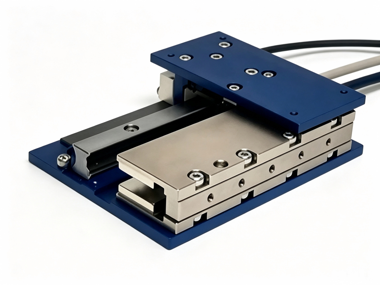
Linear Motor Sizing Calculation: Force & Acceleration Guide
Choosing the right linear motor starts with an accurate linear motor sizing calculation
A motor that is too small may not provide enough thrust or may overheat during repeated operation. A motor that is unnecessarily large can increase machine size, weight, drive requirements, and overall system cost.
So, how do you size a linear motor correctly?
For most applications, linear motor sizing comes down to two critical requirements:
Peak Force — the maximum thrust required during acceleration or deceleration.
Continuous Force — the force the motor must sustain over the complete operating cycle without exceeding its thermal limits.
To calculate these values, you first need to determine the required acceleration from the load, travel distance, travel time, and motion profile.
In practical terms, the linear motor sizing process follows this sequence:
Moving Mass + Travel Distance + Travel Time → Motion Profile → Acceleration → Peak Force → Continuous/RMS Force → Linear Motor Size
This guide walks through the complete calculation step by step.
What Do You Need to Size a Linear Motor?
Before starting the calculation, collect the basic application requirements.
Sizing Parameter
Symbol
Unit
Total moving mass
m
kg
Travel distance / stroke
S
m
Required travel time
T
s
Maximum/cruising speed
V
m/s
Acceleration
A
m/s²
Friction force
Ff
N
External force
Fext
N
Peak force
Fpeak
N
RMS force
Frms
N
Dwell time
Tdwell
s
The total moving mass should include the payload and all components that move with it, including the motor mover/forcer where applicable, tooling, mounting plates, and other moving hardware.
Once these inputs are known, you can begin calculating the required motor size.
Step 1: Calculate the Required Linear Motor Acceleration
Acceleration is one of the most important inputs in linear motor sizing because it directly determines the inertial force the motor must generate.
If acceleration is already specified, you can proceed directly to the force calculation.
But in many applications, the actual acceleration requirement is unknown.
Instead, you may know:
how far the load needs to move; and
how quickly it must complete the move.
For example:
The axis must travel 300 mm in 0.2 seconds.
In this case, acceleration can be calculated from the required travel distance, travel time, and motion profile.
Two common motion profiles are used for linear motor sizing:
Triangular Velocity Profile: acceleration followed immediately by deceleration, with no constant-speed section.
Trapezoidal Velocity Profile: acceleration, constant-speed cruising, and deceleration.
For short travel distances, a triangular velocity profile is often appropriate. For longer travel distances, a trapezoidal profile may provide a more practical motion cycle.
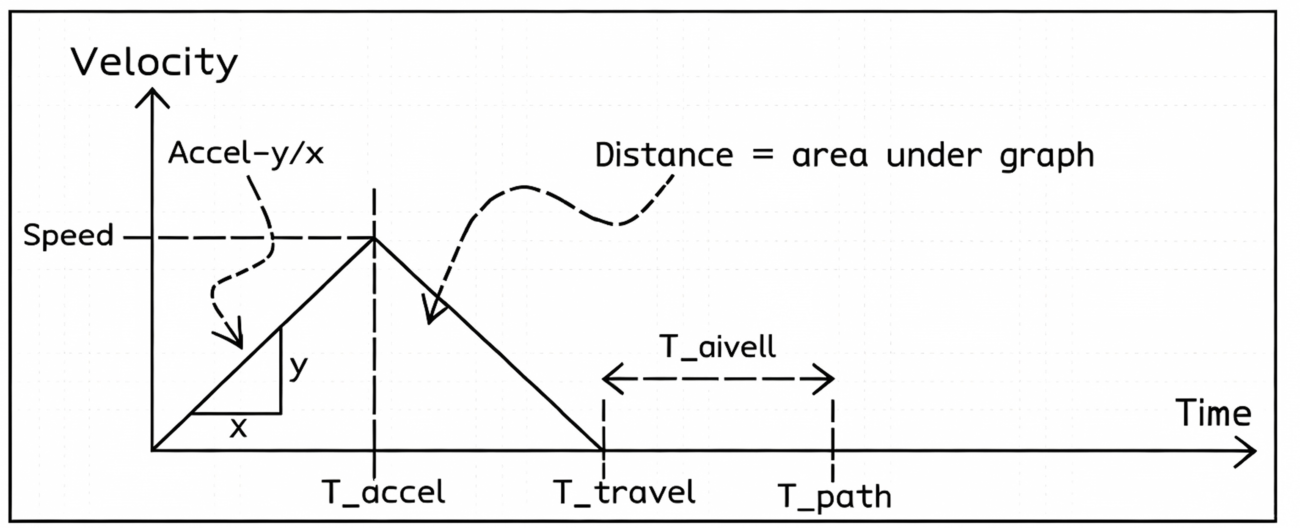
Step 2: Triangular Velocity Profile Calculation
In a triangular velocity profile, the linear motor accelerates to peak speed and then immediately begins decelerating.
There is no constant-speed or cruising phase.
For symmetrical acceleration and deceleration:
Taccel = Tdecel = Ttravel / 2
The travel distance is equal to the area under the velocity-time curve.
Because the velocity-time graph forms a triangle:
S = ½ × Vmax × T
and:
Vmax = A × T/2
Substituting this into the distance equation gives:
S = AT²/4
Therefore:
A = 4S/T²
Where:
A = required acceleration (m/s²)
S = travel distance (m)
T = total travel time (s)
Triangular Profile Example
Suppose:
Travel distance = 0.30 m
Travel time = 0.20 s
Then:
A = (4 × 0.30) / 0.20²
A = 30 m/s²
The linear motor therefore needs to accelerate the moving load at 30 m/s².
Recommended Figure
Use a Velocity-Time graph showing:
Speed / Time / T_accel / T_travel / T_dwell / T_path / Accel = ΔV/ΔT / Distance = Area Under Graph
The triangular area visually explains why:
A = 4S/T²
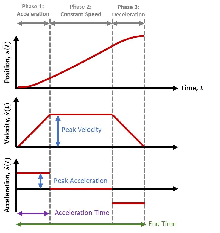
Step 3: Trapezoidal Velocity Profile Calculation
For longer moves, a trapezoidal velocity profile may be more suitable.
The motion consists of:
Acceleration → Cruising → Deceleration
Unlike a triangular profile, the motor maintains a predefined cruising velocity for part of the travel.
For a symmetrical acceleration/deceleration profile, if the cruising velocity is known:
This equation is useful when the machine designer has already defined a desired maximum or cruising speed.
Why Does This Formula Work?
The distance traveled is the area under the velocity-time curve.
For a symmetrical trapezoidal profile:
S = V × (T − Taccel)
Therefore:
Taccel = T − S/V
Since:
A = V/Taccel
we obtain:
A = V/(T − S/V)
Recommended Figure
The Velocity-Time graph should show:
Acceleration → Cruising → Deceleration → Dwell
with labels for:
Speed / T_accel / T_travel / T_dwell / T_path / Cruising Speed / Distance = Area Under Graph
Step 4: Calculate the Required Peak Force
Once acceleration is known, the next step in the linear motor sizing calculation is determining peak thrust.
The basic equation is:
Fpeak = mA + Ffriction + Fexternal
Where:
Fpeak = required peak force (N)
m = total moving mass (kg)
A = maximum acceleration (m/s²)
Ffriction = friction force (N)
Fexternal = external force acting on the axis (N)
For a simplified horizontal application where friction and external forces are negligible:
Fpeak = mA
Peak Force Sizing Example
Suppose the total moving mass, including the mover, is:
m = 2.5 kg
From the previous triangular-profile calculation:
A = 30 m/s²
Then:
Fpeak = 2.5 × 30
Fpeak = 75 N
Therefore, the application requires at least 75 N of peak motor thrust, assuming friction and external forces can be ignored.
This illustrates the most important relationship in preliminary linear motor sizing:
Peak force is primarily determined by total moving mass and maximum acceleration.
Step 5: Calculate Force During Cruising
Peak force alone is not enough to select a linear motor.
You also need to calculate the force required during each phase of the operating cycle.
During constant-speed cruising:
Acceleration = 0
Therefore, the motor does not need to generate inertial acceleration force.
However, it may still need to overcome friction and external forces:
Fcruise = Ffriction + Fexternal
For a nearly frictionless horizontal system with no external process load, cruising force may be relatively small.
But in real machines, the motor may need to continuously overcome:
guide friction
cable drag
sealing resistance
process forces
aerodynamic resistance
other mechanical loads
These forces contribute to the continuous force requirement.
Step 6: Calculate Deceleration Force
The calculation for deceleration is similar to acceleration.
For a symmetrical motion profile:
|Aaccel| = |Adecel|
However, the actual motor force during acceleration and deceleration may differ when an unbalanced force acts on the axis.
Gravity is a common example.
For vertical motion, gravity may oppose the motor in one direction and assist it in the other.
Therefore, vertical-axis linear motor sizing should calculate acceleration and deceleration forces separately.
Step 7: Calculate Force During Dwell
During dwell:
Velocity = 0
and:
Acceleration = 0
However, the required motor force is not always zero.
If an external force is acting on the motor, the servo must generate holding force to maintain position.
For example:
Fdwell = Fexternal
For a vertical axis, gravity can create a significant continuous holding-force requirement.
This is why dwell time must be included in the complete linear motor sizing calculation.
Step 8: Calculate Continuous / RMS Force
After calculating force during acceleration, cruising, deceleration, and dwell, determine the effective force requirement over the complete machine cycle.
The selected linear motor should therefore provide at least:
Peak Force: 75 N
Continuous Force: approximately 61.2 N
These values are preliminary requirements. Final selection should include an appropriate engineering margin and verification against the manufacturer’s actual force, speed, thermal, cooling, and duty-cycle specifications.
Triangular vs. Trapezoidal Profile for Linear Motor Sizing
Sizing Factor
Triangular Profile
Trapezoidal Profile
Acceleration
Yes
Yes
Cruising
No
Yes
Deceleration
Yes
Yes
Best suited for
Shorter moves
Longer moves
Required inputs
S, T
S, T, V
Acceleration formula
A = 4S/T²
A = V/(T − S/V)
Peak speed
2S/T
Predefined V
The choice of motion profile directly affects acceleration and therefore affects the required peak motor force.
This is why the motion profile should be established before selecting the linear motor size.
Linear Motor Sizing Calculation Formula Sheet
What You Need to Calculate
Formula
Triangular acceleration
A = 4S/T²
Triangular peak speed
Vmax = 2S/T
Trapezoidal acceleration
A = V/(T − S/V)
Peak force
Fpeak = mA + Ffriction + Fexternal
Cruising force
Fcruise = Ffriction + Fexternal
Dwell force
Fdwell = Fexternal
RMS force
Frms = √(ΣFi²ti/Tpath)
For vertical or inclined applications, include the gravitational force acting along the direction of motion.
How to Choose a Linear Motor After the Calculation
Once the required peak and continuous forces have been calculated, compare them with the manufacturer’s motor specifications.
At minimum, verify:
Peak Force: Can the motor provide the required acceleration and deceleration thrust?
Continuous Force: Can the motor handle the calculated RMS force without overheating?
Maximum Speed: Can the motor achieve the required peak or cruising velocity?
Stroke: Does the motor configuration support the required travel distance?
Duty Cycle: Can the motor sustain the required repetitive motion?
Cooling Conditions: Are the published continuous-force ratings based on natural cooling, forced-air cooling, or water cooling?
The motor should satisfy the required operating point under the actual installation and cooling conditions, not simply exceed one force value on the datasheet.
Common Linear Motor Sizing Mistakes
One of the most common mistakes is selecting a linear motor based only on payload. Payload alone does not determine motor size — acceleration is equally important.
Another common mistake is checking only peak force. A motor may provide enough thrust for acceleration but still overheat if its continuous force rating is below the application’s RMS force requirement.
Engineers should also avoid ignoring cruising and dwell loads. Even when acceleration is zero, the motor may still generate force to overcome friction, process loads, or gravity.
Finally, always use the total moving mass, not just the payload mass, when calculating acceleration force.
Linear Motor Sizing Calculation FAQ
How do I calculate what size linear motor I need?
Calculate the required acceleration first, then determine peak force using F = mA + friction + external forces. Finally, calculate RMS force over the complete duty cycle and select a motor whose peak and continuous force ratings exceed these requirements.
How do you calculate peak force for a linear motor?
Use Fpeak = mA + Ffriction + Fexternal. For vertical or inclined axes, include the gravitational force acting along the direction of travel.
How do you calculate acceleration for linear motor sizing?
For a symmetrical triangular velocity profile, use A = 4S/T². For a symmetrical trapezoidal profile with a predefined cruising velocity, use A = V/(T − S/V).
What is the difference between peak force and continuous force in linear motor sizing?
Peak force is the maximum short-duration thrust required during the motion cycle. Continuous force is the force the motor can sustain thermally over repeated operation.
Should I use peak force or RMS force to size a linear motor?
Use both. Peak force determines whether the motor can perform the most demanding part of the move, while RMS force determines whether it can handle the complete duty cycle thermally.
How do I size a linear motor when acceleration is unknown?
Use the required travel distance and travel time to establish a triangular or trapezoidal velocity profile, then calculate the required acceleration from that profile.
Is a triangular or trapezoidal velocity profile better for linear motor sizing?
A triangular profile is often suitable for short moves where there is little or no time for cruising. A trapezoidal profile is useful for longer moves where the motor can maintain a constant-speed section.
Does dwell time affect linear motor sizing?
Yes. If the motor must resist gravity or another external force while stationary, dwell force contributes to the RMS and continuous-force requirement.
Conclusion: A Simple Linear Motor Sizing Process
A reliable linear motor sizing calculation can be summarized in five steps:
1. Define moving mass, travel distance, and travel time.
2. Select a triangular or trapezoidal motion profile.
3. Calculate the required acceleration.
4. Calculate peak force during acceleration and deceleration.
5. Calculate RMS force over the complete cycle and compare it with the motor’s continuous force rating.
The key relationship is:
Motion Requirements → Acceleration → Peak Force → RMS Force → Motor Size
For a triangular motion profile:
A = 4S/T²
For a trapezoidal motion profile:
A = V/(T − S/V)
And once acceleration is known:
Fpeak = mA + Ffriction + Fexternal
By calculating both peak force and continuous force, you can narrow down the appropriate linear motor size before performing final verification against the manufacturer’s force-speed and thermal specifications.
HCY Automation delivers integrated solutions across motion control, linear motion, robotics, machine vision, pneumatic systems, and precision gearboxes to help global manufacturers build smarter, faster, and more reliable production lines. Our engineering team helps you select and integrate the right motion control, robotics, and automation components for your specific application.