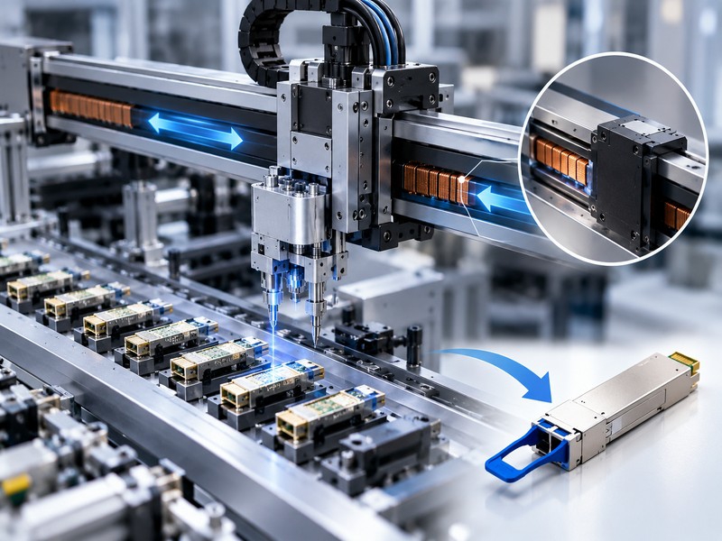
Linear Motor Selection Guide: How to Choose the Right Linear Motor
Learn how to select and size a linear motor based on force, speed, acceleration, precision, stroke, thermal performance, feedback, environment, and application requirements.
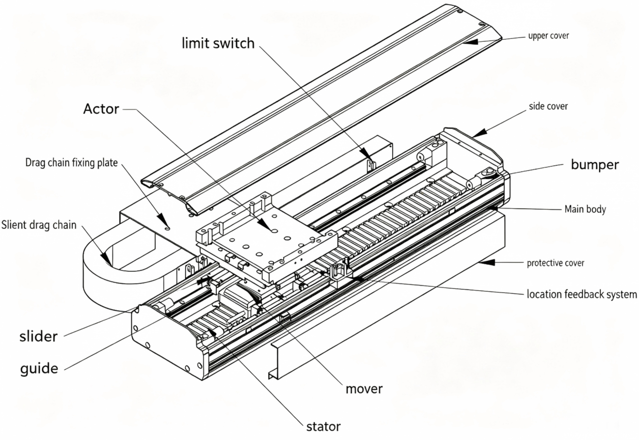
Choosing the right linear motor is not simply a matter of finding the motor with the highest thrust or the fastest rated speed. A properly selected linear motor must work as part of a complete motion system—including the motor, drive, encoder, linear guide, mechanical structure, cooling system, and motion-control software.
For high-speed automation, semiconductor equipment, precision inspection, packaging machinery, machine tools, robotics, and other demanding applications, the key question is:
Can the linear motor deliver the required force, speed, acceleration, precision, and thermal performance throughout the complete motion cycle?
This guide explains how to select and size a linear motor step by step, what specifications matter most, common selection mistakes, and how to validate a motor before mass production.
What Is a Linear Motor?
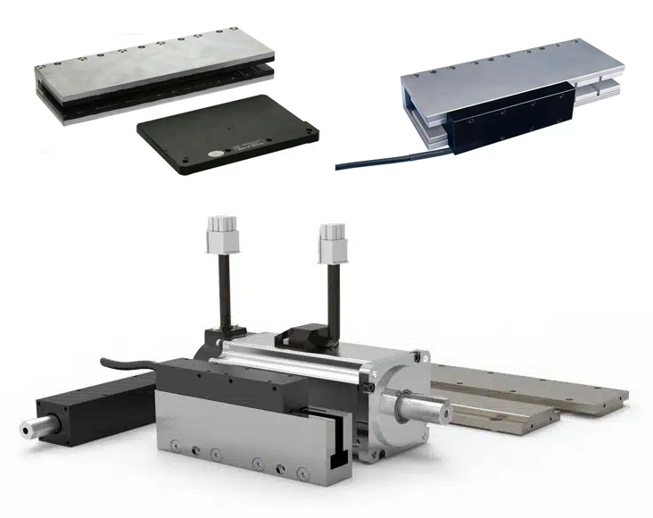
A linear motor is essentially a rotary motor that has been “unrolled” to produce linear force directly.
Unlike a conventional rotary motor combined with a ball screw, belt, rack-and-pinion, or gearbox, a direct-drive linear motor converts electrical energy directly into linear motion.
This eliminates many mechanical transmission components and can provide:
High acceleration
High maximum speed
Zero mechanical backlash
High positioning accuracy
Excellent dynamic response
Low mechanical wear in the drive mechanism
Flexible long-stroke configurations
However, eliminating the mechanical transmission does not automatically guarantee higher system accuracy. The final performance depends on the complete motion system, including the mechanical structure, encoder, servo drive, control loop, thermal behavior, and force ripple.
For this reason, linear motor selection should always be treated as a system-level engineering problem rather than a motor-only decision
The Four Most Important Linear Motor Selection Criteria
At the beginning of a project, engineers should focus on four fundamental requirements:
Force
Speed and acceleration
Positioning accuracy and repeatability
Thermal performance and service life
These four parameters provide the foundation for motor sizing.
But in real applications, several additional factors can determine whether a selected motor actually performs as expected.
1. Linear Motor Force: Peak Force vs. Continuous Force
Force is usually the first parameter engineers look at—but it is also one of the most commonly misunderstood.
A linear motor datasheet normally provides at least two important force ratings:
Peak force
Continuous force
Peak Force
Peak force is the maximum force the motor can generate for a limited period.
It is mainly important during:
Rapid acceleration
Rapid deceleration
High-load positioning
Short-duration process forces
Dynamic trajectory changes
For example, a high-speed pick-and-place machine may require very high peak thrust during acceleration but relatively little force while moving at constant velocity.
Continuous Force
Continuous force is the force the motor can sustain under the specified thermal conditions.
It is strongly related to:
Winding temperature
Copper losses
Thermal resistance
Cooling method
Ambient temperature
Duty cycle
RMS force
Therefore, a motor with a very high peak thrust rating may still be unsuitable for a high-duty-cycle application.
This is one of the most important rules in linear motor sizing:
Peak force determines whether the motor can perform the dynamic move. Continuous/RMS force determines whether it can survive the complete duty cycle thermally.
Engineering sizing guides similarly recommend calculating the motion profile first and comparing both peak force and RMS force against the motor’s ratings
2. How to Calculate Linear Motor Force
or a simple horizontal axis, the required motor force can be approximated as:
F = ma + Ff + Fext
Where:
F = required motor force
m = total moving mass
a = required acceleration
Ff = friction and guide resistance
Fext = external process force
For a vertical axis, gravity must also be considered:
F = ma + mg + Ff + Fext
The direction of each force must be considered carefully.
Example
Suppose:
Moving mass = 10 kg
Required acceleration = 5 m/s²
Friction = 10 N
External process force = 20 N
The acceleration force is:
Facc = 10 × 5 = 50 N
Therefore:
Frequired = 50 + 10 + 20 = 80 N
The selected motor must have sufficient peak force for this dynamic requirement, while its continuous capability must also satisfy the thermal requirements of the entire motion cycle.
Do not forget to include the mass of the moving motor component itself. In high-acceleration applications, the motor’s moving mass can become a significant part of the total inertia.
3. Why RMS Force Matters for Linear Motor Sizing
A machine rarely operates at maximum force continuously.
A typical motion cycle may contain:
Acceleration
Constant-speed travel
Deceleration
Dwell
Return motion
The motor force therefore changes continuously.
For a simplified duty cycle, RMS force can be calculated as:
Long-stroke applications may require modular magnetic tracks, longer guide systems, cable management, and additional structural considerations.
Maximum Speed
Maximum speed is normally specified in m/s.
However, the maximum achievable speed is influenced by more than the motor’s mechanical capability.
It can also be limited by:
Back EMF
DC bus voltage
Drive voltage capability
Motor winding
Encoder bandwidth
Cable management
Mechanical resonance
Bearing or guide limitations
5. Acceleration Is Not the Same as Acceleration Time
This is an important technical distinction.
Acceleration is measured in:
m/s²
Acceleration describes how quickly velocity changes.
Acceleration time is measured in:
seconds
For example, if a stage accelerates from 0 to 2 m/s in 0.2 seconds:
a = Δv / Δt
a = 2 / 0.2 = 10 m/s²
Therefore, when requesting a linear motor quotation or sizing calculation, provide both the required velocity and the required acceleration or motion time.
Linear Motor Sizing Workflow
Step 1: Define the Application
Determine:
Payload
Moving mass
Stroke
Orientation
Process force
Required lifetime
Operating environment
Step 2: Define the Motion Profile
Determine:
Maximum velocity
Acceleration
Deceleration
Cycle time
Dwell time
Repetition frequency
Step 3: Calculate Required Force
Calculate acceleration, friction, gravity, and external process forces.
Step 4: Calculate Peak and RMS Force
Confirm:
Peak motor force > required peak force
and
Continuous motor force > required RMS force
with appropriate engineering margin.
Step 5: Check Speed and Voltage
Verify that the motor and drive can achieve the required maximum speed considering back EMF and available bus voltage.
Step 6: Check Thermal Performance
Evaluate:
RMS current
Winding temperature
Thermal resistance
Ambient temperature
Cooling method
Duty cycle
Step 7: Select Encoder and Guide System
Match:
Encoder resolution
Accuracy
Feedback bandwidth
Guide load capacity
Magnetic attraction
Mechanical stiffness
Step 8: Validate the Complete System
Common Linear Motor Selection Mistakes
Mistake #1: Selecting a Motor by Peak Thrust Alone
A datasheet may advertise an impressive peak thrust value.
But peak thrust may only be available for a limited period.
Mistake #2: Assuming a High-Resolution Encoder Guarantees High Accuracy
A high-resolution encoder is valuable, but it cannot compensate for:
Mechanical resonance
Structural deformation
Thermal expansion
Poor installation
Force ripple
Poor servo tuning
Mistake #3: Ignoring Magnetic Attraction Force
This is particularly important with iron-core flat linear motors.
The magnetic attraction force can significantly load the guide system.
Mistake #4: Ignoring Motor Moving Mass
In high-acceleration applications, the moving portion of the motor is part of the accelerated mass.
Ignoring it can lead to an underestimated force requirement.
Mistake #5: Treating Maximum Speed as the Only Dynamic Requirement
Two machines may have the same maximum speed but completely different performance requirements.
For example:
Machine A reaches 2 m/s slowly.
Machine B reaches 2 m/s in 50 ms.
Machine B requires significantly higher acceleration and peak force.
Mistake #6: Ignoring Thermal Conditions
A continuous-force rating is meaningful only under its specified thermal conditions.
If the machine operates at:
40°C ambient
High duty cycle
Poor heat dissipation
Enclosed installation
the actual continuous capability may be lower than the catalog value.
Mistake #7: Treating Installation Tolerances as an Afterthought
Incorrect flatness, alignment, parallelism, or air gap can reduce motor performance and create mechanical problems.
Better approach: design adjustment mechanisms and measurement procedures into the machine from the beginning.
Linear Motor Maintenance and Operation
Although linear motors eliminate many mechanical transmission components, they are not completely maintenance-free.
Before operation, check:
Motor mounting
Air gap
Encoder installation
Electrical connections
Grounding
Cable routing
Guide alignment
Cooling system
Environmental protection
During operation, monitor:
Motor temperature
Vibration
Noise
Position error
Following error
Current
Abnormal force behavior
Periodic maintenance should include:
Cleaning exposed surfaces
Checking connectors
Inspecting cables
Checking guides
Verifying encoder condition
Checking cooling performance
Lubricating guide components where required
Linear Motor Applications
Semiconductor Equipment
Wafer inspection
Wafer handling
Die inspection
Lithography-related positioning
Precision stages
Factory Automation
Pick-and-place systems
High-speed sorting
Packaging
Assembly
Material handling
Machine Tools
Linear motors can provide high dynamic response and eliminate mechanical transmission elements in suitable machine architectures.
Inspection and Metrology
Applications such as optical inspection and precision measurement can benefit from smooth motion and high-resolution feedback.
Robotics
Linear motors can also be used in high-speed Cartesian motion systems and other precision automation platforms.
The Future of Linear Motor Selection: Think in Systems, Not Components
The trend is moving toward:
Higher speed
Higher acceleration
Higher positioning accuracy
Lower vibration
Higher throughput
Lower energy consumption
Longer service life
Smarter servo control
More compact machine architectures
As performance requirements increase, selecting a linear motor by one specification becomes increasingly unreliable.
The real optimization target is the complete system:
Motor + Drive + Encoder + Guide + Structure + Cooling + Control Algorithm + Environment
Final Thoughts: How to Select the Right Linear Motor
A good linear motor selection process should answer five questions:
Can the motor provide the required peak force?
Can it provide the required RMS/continuous force without overheating?
Can the motor and drive reach the required speed and acceleration?
Can the encoder, mechanics, and control system achieve the required precision?
Can the complete system maintain these specifications throughout its intended service life?
Don’t select the biggest linear motor. Select the right linear motor for the complete motion profile.
Frequently Asked Questions About Linear Motor Selection
What is the most important parameter when selecting a linear motor?
There is no single most important parameter. Peak force, continuous/RMS force, maximum speed, acceleration, precision, thermal performance, and feedback requirements should be evaluated together.
How do I calculate the required linear motor thrust?
Start with the motion profile and calculate acceleration force:
F = ma
Then add friction, gravity where applicable, and external process forces.
Is peak force or continuous force more important?
Both are important. Peak force determines short-duration dynamic capability, while continuous/RMS force determines long-term thermal capability.
How do I calculate RMS force for a linear motor?
Divide the motion cycle into force/time segments and calculate the square root of the time-weighted mean square force:
F_RMS = √[Σ(Fᵢ²tᵢ)/T]
Is an ironless linear motor better than an iron-core motor?
Not necessarily. Ironless motors are attractive for smooth, high-dynamic motion, while iron-core motors can provide higher force density. The correct choice depends on the application.
Does a higher-resolution encoder always provide better positioning accuracy?
No. Encoder resolution is only one part of system performance. Mechanical accuracy, thermal expansion, vibration, servo tuning, force ripple, and structural stiffness also affect actual positioning accuracy.
Why does a linear motor need a linear encoder?
A direct-drive linear motor does not inherently provide absolute position information. A linear encoder provides position feedback to the servo controller, enabling closed-loop positioning and motion control.
Why is magnetic attraction important?
Iron-core linear motors can generate significant normal magnetic force between the motor and magnetic track. This additional load must be considered when selecting the linear guide and mechanical structure.
In many applications, yes. Linear motors can be particularly advantageous when high speed, high acceleration, long stroke, or high dynamic response is required. However, ball screws may remain more economical or advantageous for some applications.
What should I provide to a linear motor manufacturer?
At minimum, provide payload, moving mass, stroke, maximum speed, acceleration, duty cycle, installation orientation, external force, required accuracy, ambient temperature, available drive voltage, and cooling conditions.
HCY Automation delivers integrated solutions across motion control, linear motion, robotics, machine vision, pneumatic systems, and precision gearboxes to help global manufacturers build smarter, faster, and more reliable production lines. Our engineering team helps you select and integrate the right motion control, robotics, and automation components for your specific application.