How to Choose a Linear Motor for High-Precision Positioning Stages
A Practical Engineering Guide to Motor Selection, Positioning Accuracy, Speed, and Precision Motion Control
As manufacturing processes become increasingly demanding, high-precision positioning stages are playing a more important role in semiconductor equipment, optical alignment, photonics, laser processing, automated inspection, and precision assembly.
Among the available motion technologies, linear motors have become a preferred drive solution for applications requiring high speed, fast acceleration, precise positioning, and smooth motion.
However, selecting a linear motor for a high-precision positioning stage involves more than comparing motor thrust or maximum speed. The motor must work together with the mechanical structure, linear guide system, position feedback device, and motion controller to achieve the required performance.
Should you choose an iron-core or ironless linear motor? How much thrust is actually required? Does a higher-resolution encoder always mean better positioning accuracy?
This guide explains the key engineering considerations for selecting a linear motor and configuring a high-precision positioning stage for your application.
1. Why Choose a Linear Motor for High-Precision Positioning Stages?
Unlike conventional rotary motors, which require mechanical transmission components such as ball screws, belts, or gear systems to generate linear motion, a linear motor produces thrust directly along a straight path.
This direct-drive configuration eliminates many mechanical transmission components, reducing backlash, transmission errors, and mechanical wear.
For high-precision positioning applications, these characteristics provide several important advantages.
High Positioning Accuracy and Repeatability
A linear motor combined with a high-resolution linear encoder and a properly configured servo control system can achieve micron-level or even sub-micron positioning performance.
Since there is no mechanical transmission mechanism between the motor and the moving platform, errors associated with screw pitch variation, backlash, and coupling transmission can be reduced.
The actual positioning accuracy still depends on the mechanical structure, encoder accuracy, thermal stability, control parameters, and installation conditions.
High Speed and Acceleration
Linear motors provide direct electromagnetic thrust, making them suitable for applications requiring rapid movement, frequent acceleration and deceleration, and short positioning cycles.
They are widely used in high-speed scanning systems, semiconductor inspection equipment, optical alignment platforms, and automated production equipment.
Smooth Motion and Low Mechanical Wear
With no conventional mechanical transmission components, linear motor stages can provide smooth, continuous motion with minimal mechanical contact in the drive system.
This is particularly important for precision applications involving fine scanning, optical alignment, and delicate positioning operations.
Flexible Stroke Length
Linear motor systems can use modular magnetic tracks to accommodate different travel lengths.
By extending the magnetic track and mechanical structure, engineers can configure long-travel positioning stages without being restricted by the standard screw length limitations of conventional ball screw systems.
Flexible Multi-Axis Configuration
Linear motor stages can be integrated into XY, XYZ, and gantry positioning systems.
This makes them suitable for applications requiring synchronized multi-axis movement, large working areas, and high positioning accuracy.
2. Iron-Core vs. Ironless Linear Motors: Which One Should You Choose?
One of the first decisions when selecting a linear motor is choosing between an iron-core and an ironless design.
Both technologies can deliver high-performance direct-drive motion, but their electromagnetic structures and operating characteristics are different.
Iron-Core Linear Motor
An iron-core linear motor uses electromagnetic coils wound around an iron core. The iron core helps concentrate magnetic flux and generate high electromagnetic force.
Key characteristics:
High thrust density and strong force output.
Suitable for relatively heavy loads.
High acceleration capability.
Compact motor configuration for applications requiring substantial thrust.
Magnetic attraction force between the motor and magnetic track must be considered during mechanical design.
Gantry systems handling relatively heavy workpieces.
High-load material handling and positioning equipment.
For applications where payload capacity and thrust requirements are the primary considerations, an iron-core linear motor can be a suitable choice.
Ironless Linear Motor
An ironless linear motor uses a coil assembly without an iron core. Its electromagnetic design eliminates the cogging force associated with iron-core structures.
Key characteristics:
Zero cogging force from the iron-core structure.
Smooth and stable motion.
Low moving mass.
Excellent dynamic response.
Suitable for applications requiring fine motion control and high acceleration.
No iron-core attraction force acting on the magnetic track.
Typical applications:
Optical alignment platforms.
Semiconductor inspection equipment.
Precision measurement systems.
Photonics packaging equipment.
High-speed scanning and positioning systems.
Precision assembly and automated testing equipment.
For applications where smooth motion, low velocity fluctuation, and precise positioning are critical, an ironless linear motor is often a strong option.
Iron-Core vs. Ironless Linear Motor Comparison
Selection factor
Iron-Core
Ironless
Thrust density
High
Generally lower
Cogging force
May be present
No iron-core cogging
Magnetic attraction
Present
No iron-core attraction
Motion smoothness
Depends on motor and control design
Excellent
Moving mass
Depends on configuration
Generally lower
Heavy-load applications
Well suited
Depends on thrust requirements
Precision scanning
Suitable with proper design
Particularly suitable
Typical applications
Heavy-duty positioning and gantry systems
Optical alignment and precision motion
Engineering recommendation:
There is no universally better linear motor.
Choose an iron-core motor when high thrust and load capacity are priorities. Consider an ironless motor when smooth motion, low cogging, and high dynamic response are more important.
The final selection should be based on the complete motion system rather than the motor type alone.
3. Six Key Factors When Selecting a Linear Motor for a Precision Positioning Stage
Choosing the right linear motor requires evaluating the entire application, including payload, motion profile, positioning requirements, mechanical configuration, and operating environment.
The following six factors provide a practical selection framework.
3.1 Payload and Required Thrust
Payload is one of the most important parameters in linear motor selection.
Before selecting a motor, engineers should identify:
Total moving mass, including the workpiece, fixture, moving platform, and motor components.
Maximum acceleration and deceleration.
Friction and resistance from the linear guide system.
Cable drag and other external forces.
Installation orientation, especially horizontal or vertical movement.
The required thrust can be estimated using Newton’s second law:
F = m × a + Fᵣ
Where:
F = Required driving force (N).
m = Total moving mass (kg).
a = Acceleration (m/s²).
Fᵣ = Total resistance, including friction and other external forces (N).
For vertical applications, gravity must also be included in the force calculation.
For example, a precision positioning stage with a moving mass of 20 kg and a target acceleration of 5 m/s² requires:
F = 20 × 5 = 100 N
This is the theoretical acceleration force before adding friction, external resistance, and engineering safety margins.
Engineers should also distinguish between peak thrust and continuous thrust. Peak thrust is relevant during short acceleration periods, while continuous thrust determines whether the motor can operate without exceeding its thermal limits.
HCY engineering insight: Selecting a linear motor based only on payload weight can result in insufficient dynamic performance or excessive motor heating. The complete motion profile should always be considered.
3.2 Speed and Acceleration Requirements
Different applications have different motion requirements.
For example:
Semiconductor inspection requires rapid movement and precise stopping.
Optical alignment requires smooth, controlled movement at very low speeds.
Laser processing requires stable scanning and accurate trajectory control.
Automated assembly requires a balance between positioning accuracy and cycle time.
When evaluating motor performance, consider:
Maximum operating speed.
Maximum acceleration and deceleration.
Continuous operating speed.
Settling time after movement.
Motion smoothness at low velocity.
A motor with a high maximum speed does not necessarily provide better positioning performance.
In precision applications, the ability to accelerate quickly, decelerate smoothly, and settle accurately at the target position is often more important than maximum speed alone.
3.3 Positioning Accuracy, Repeatability, and Resolution
These three parameters are frequently confused, but they describe different aspects of positioning performance.
Positioning Accuracy
Positioning accuracy describes how closely the actual position approaches the commanded target position.
For example, a positioning accuracy of ±2 µm means the positioning error is within 2 µm under the specified measurement conditions.
Repeatability
Repeatability describes how consistently the stage returns to the same position over multiple movements.
For example, a bidirectional repeatability of ±0.5 µm indicates the stage can repeatedly approach the target within the specified tolerance under defined conditions.
Resolution
Resolution refers to the smallest position increment that a measurement or control system can detect or command.
A high-resolution encoder does not automatically guarantee high positioning accuracy.
Actual performance depends on several factors:
Linear encoder accuracy.
Encoder resolution and interpolation.
Mechanical straightness and flatness.
Guide system precision.
Thermal expansion.
Servo tuning and control stability.
Installation and calibration conditions.
For applications requiring micron-level or sub-micron positioning, a high-accuracy linear encoder with closed-loop feedback is generally recommended.
In more demanding applications, laser interferometer calibration may also be used to verify actual positioning performance.
3.4 Stroke Length and Mechanical Configuration
The required travel distance determines the overall stage structure and motor configuration.
Linear motor positioning stages can be designed for short-stroke precision movement or long-travel applications.
Typical configurations include:
Single-axis linear positioning stages.
XY precision positioning stages.
XYZ multi-axis positioning systems.
Dual-axis gantry systems.
Multi-axis precision alignment platforms.
For long-travel applications, modular magnetic tracks offer flexibility in system configuration.
For gantry systems, engineers must also consider:
Beam stiffness.
Structural deformation.
Cross-axis synchronization.
Moving mass distribution.
Installation accuracy.
Vibration during acceleration and deceleration.
A longer travel distance does not automatically mean better performance. Mechanical rigidity and thermal stability become increasingly important as the stage size increases.
3.5 Linear Guide System and Mechanical Rigidity
The linear motor generates the driving force, but the guide system determines how accurately and stably the moving platform travels.
The choice of linear guide directly affects straightness, flatness, load capacity, friction, and dynamic performance.
Common guide technologies include:
Cross-Roller Linear Guides
Cross-roller guides provide high rigidity, good load capacity, and precise linear guidance. They are commonly used in compact precision positioning stages.
Ball Bearing Linear Guides
These guides offer a practical balance between load capacity, speed, rigidity, and cost. They are widely used in industrial linear motion systems.
Air Bearings
Air bearing systems use a thin layer of pressurized air to support the moving platform without conventional mechanical contact.
Their key advantages include:
Extremely low friction.
No mechanical contact during normal operation.
Excellent motion smoothness.
High straightness and flatness potential.
Suitability for ultra-precision positioning applications.
Air bearing linear motor stages are particularly suitable for advanced optical systems, semiconductor manufacturing, precision metrology, and other applications requiring exceptionally smooth motion.
However, they require a suitable compressed air supply, clean operating conditions, and careful mechanical design.
3.6 Operating Environment and Thermal Management
Environmental conditions can significantly influence positioning accuracy.
Important considerations include:
Ambient temperature.
Temperature variation during operation.
Dust and contamination.
Humidity.
Vacuum requirements.
Electromagnetic interference.
Cooling requirements.
Linear motors generate heat during operation. If this heat is not properly managed, thermal expansion can affect the motor structure, encoder mounting, and positioning accuracy.
For high-precision applications, engineers may need to consider:
Motor cooling methods.
Thermal isolation.
Temperature monitoring.
Low-expansion structural materials.
Heat dissipation design.
Encoder installation and thermal compensation.
For vacuum applications, the selection of lubricants, cables, materials, and other components must also meet the specified vacuum requirements.
A positioning stage should therefore be designed for its actual working environment, not simply selected from standard performance specifications.
4. How to Build a Complete High-Precision Linear Motor Positioning Stage
Selecting the motor is only one part of the engineering process.
A high-performance linear motor positioning stage is an integrated motion system consisting of several essential components.
4.1 Linear Motor and Magnetic Track
The linear motor provides direct electromagnetic driving force.
Motor selection should match the required thrust, moving mass, acceleration, speed, and duty cycle.
The magnetic track configuration must also be compatible with the required stroke length and mechanical structure.
4.2 Precision Linear Guide
The guide system supports the moving platform and controls its motion trajectory.
Depending on the application, engineers can select cross-roller guides, ball bearing linear guides, or air bearings.
The required load capacity, moment ratings, straightness, flatness, and rigidity should all be evaluated.
4.3 Linear Encoder and Position Feedback
A linear encoder provides real-time position feedback for closed-loop control.
Compared with relying only on motor-side rotary feedback, direct linear position measurement can help compensate for position errors between the motor and the moving platform.
For high-precision positioning stages, the encoder’s accuracy, resolution, mounting position, and environmental compatibility should be carefully considered.
4.4 Servo Drive and Motion Controller
The servo drive controls motor current and generates the required electromagnetic force.
The motion controller manages positioning commands, acceleration profiles, synchronization, and multi-axis coordination.
Proper servo tuning is essential to achieve stable motion, short settling times, and accurate positioning.
4.5 Mechanical Base and Structural Design
The mechanical base directly influences the overall positioning performance.
Common structural materials include aluminum alloy, steel, cast iron, and granite.
Material selection should consider:
Structural rigidity.
Thermal expansion.
Vibration damping.
Weight limitations.
Machining accuracy.
Installation requirements.
For demanding precision applications, the mechanical structure may require precision machining, stress relief, and geometric calibration.
The key principle: High positioning accuracy is achieved through the coordinated design of the motor, guide system, encoder, controller, and mechanical structure. Replacing only the motor cannot guarantee the required system performance.
5. Typical Applications of Linear Motor Precision Positioning Stages
Linear motor stages are widely used in industries where motion accuracy, speed, and stability directly affect product quality and manufacturing efficiency.
Linear motor stages are suitable for wafer inspection, precision measurement, optical inspection, and semiconductor automation systems.
Photonics and Optical Alignment
Photonics manufacturing requires accurate alignment of optical components, fiber arrays, laser devices, and optical modules.
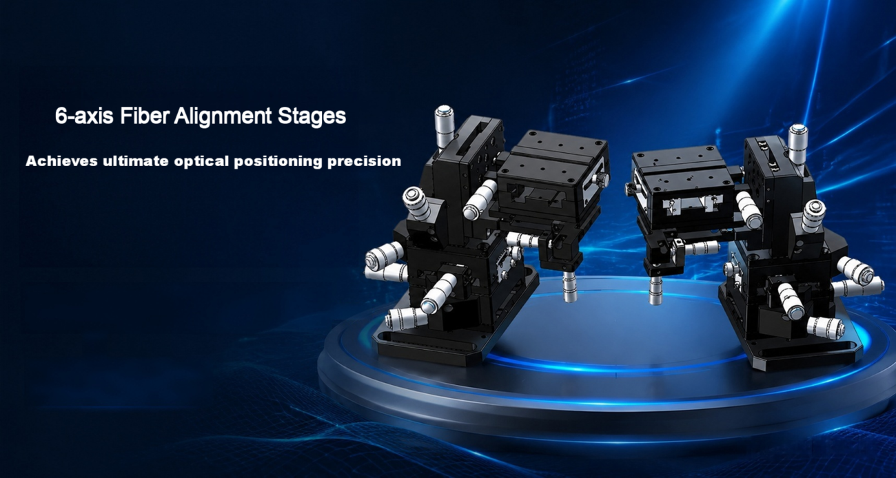
Linear motor positioning stages can provide smooth, precise multi-axis movement for optical alignment, active fiber alignment, and photonic device assembly.
For applications requiring extremely fine adjustment, linear motor stages can also be combined with piezoelectric positioning mechanisms.
Laser Processing and Microfabrication
Laser processing equipment requires accurate positioning and stable scanning trajectories.
Linear motor-driven XY and gantry platforms are suitable for laser cutting, laser marking, micromachining, and precision material processing.
Automated Optical Inspection (AOI)
Automated optical inspection systems require accurate movement between inspection positions and stable scanning performance.
Linear motor stages help improve inspection efficiency while maintaining consistent positioning.
Precision Assembly and Automated Testing
In electronic assembly and automated testing equipment, positioning accuracy and cycle time are both important.
Linear motor stages can be integrated into multi-axis automation systems for component alignment, precision dispensing, measurement, and functional testing.
6. Linear Motor vs. Ball Screw: Which Is Better for Precision Positioning?
Linear motors and ball screw-driven stages are both widely used in industrial automation.
However, their advantages differ depending on the application’s performance requirements.
Comparison
Linear Motor Stage
Ball Screw Stage
Drive method
Direct drive
Mechanical transmission
Backlash
No screw transmission backlash
Depends on screw and nut design
Speed
High
Depends on screw lead and critical speed
Acceleration
High
Limited by rotating inertia and mechanical design
Motion smoothness
Excellent with proper control
Depends on screw and guide quality
Maintenance
No screw lubrication or wear in the drive transmission
Requires screw and bearing maintenance
Long stroke
Flexible modular configuration
Screw length and critical speed limitations
System cost
Generally higher
Generally more economical
Typical applications
High-speed precision positioning
General industrial positioning and precision automation
Which technology should you choose?
Choose a linear motor stage when your application requires:
High acceleration and rapid positioning.
Smooth motion at very low speeds.
High-speed scanning.
Reduced mechanical transmission errors.
Long travel with high dynamic performance.
Consider a ball screw stage when your application requires:
Cost-effective precision positioning.
Moderate operating speed.
High thrust in a compact configuration.
A proven and practical industrial motion solution.
Neither technology is universally superior. The best solution depends on the required accuracy, speed, load, travel distance, operating cycle, and overall equipment budget.
7. Common Mistakes to Avoid When Selecting a Linear Motor
Even when the motor specifications appear suitable, an improperly configured positioning stage may fail to achieve the expected performance.
Here are five common selection mistakes.
1. Selecting a motor based only on maximum thrust
Peak thrust and continuous thrust are different. Ignoring duty cycle and thermal limitations can result in overheating and reduced performance.
Encoder resolution describes the smallest measurable increment, not the actual accuracy of the complete positioning system.
3. Ignoring mechanical rigidity
A high-performance linear motor cannot compensate for insufficient structural stiffness, guide deformation, or vibration.
4. Overlooking thermal effects
Temperature changes can cause dimensional variation and positioning drift, especially in micron-level applications.
5. Treating multi-axis stages as simple combinations of single-axis modules
XY, XYZ, and gantry systems require careful consideration of load distribution, center of gravity, moment capacity, structural deformation, and axis synchronization.
A complete engineering evaluation should always be performed before finalizing the configuration.
8. Customized Linear Motor Positioning Solutions from HCY Automation
At HCY Automation, we understand that different precision applications require different motion configurations.
A standard linear motor stage may not always meet the required travel, load capacity, positioning accuracy, or installation dimensions.
We provide industrial linear motion and precision positioning solutions tailored to equipment manufacturers, automation system integrators, and industrial customers.
Our engineering-oriented approach focuses on matching the motion system to the actual application requirements.
Our positioning solutions can include:
Linear motor stages: Iron-core and ironless configurations.
Precision linear stages: Single-axis, XY, and XYZ configurations.
Gantry positioning systems: Customized travel and structural arrangements.
Precision alignment platforms: Solutions for optical and photonics applications.
Motion control integration: Motors, servo drives, encoders, and motion controllers.
Customized mechanical structures: Platform dimensions, mounting interfaces, and load configurations.
Whether you need a compact precision positioning stage for optical alignment or a large-travel linear motor gantry for automated inspection, HCY can help evaluate the mechanical and motion requirements and develop a suitable configuration.
Looking for a linear motor positioning stage for your next project?
Share your application requirements with our engineering team.
To help us evaluate the right solution, please provide:
Required travel distance (stroke).
Total moving load and payload.
Target positioning accuracy and repeatability.
Required maximum speed and acceleration.
Number of motion axes.
Installation orientation and available space.
Working environment and application details.
Based on these parameters, we can help assess the motor type, guide system, encoder configuration, and overall positioning stage design.
HCY Automation – Your Partner for Industrial Linear Motion, Motion Control, and Precision Positioning Solutions.
Contact us to discuss your customized linear motor positioning requirements.
Frequently Asked Questions (FAQ)
1. What is the difference between an iron-core and an ironless linear motor?
An iron-core linear motor uses an iron core to concentrate magnetic flux and generate high thrust density. It is suitable for applications requiring relatively high force output.
An ironless linear motor has no iron core in its coil assembly, eliminating iron-core cogging and attraction force. It is particularly suitable for smooth, precise motion and high-dynamic applications.
2. Can a linear motor achieve sub-micron positioning accuracy?
Yes. A properly designed linear motor positioning system can achieve sub-micron positioning performance.
However, the final accuracy depends on the motor, mechanical structure, linear encoder, servo control, thermal stability, and calibration conditions.
3. What encoder is suitable for a high-precision linear motor stage?
A high-accuracy optical linear encoder is commonly used in precision positioning systems.
The encoder should be selected according to the required measurement accuracy, resolution, travel length, environmental conditions, and control requirements.
Laser interferometers can also be used for precision calibration and performance verification.
4. Are linear motors suitable for long-travel positioning applications?
Yes. Linear motor systems can use modular magnetic tracks to accommodate different travel lengths.
The mechanical structure, thermal behavior, cable management, and encoder configuration must also be designed to support the required stroke.
5. What is the difference between a linear motor stage and a linear actuator?
A linear motor stage is generally designed for precise, controlled linear movement and often integrates a linear guide, position feedback, and servo control.
A linear actuator is a broader term referring to devices that generate linear motion. It may use a ball screw, belt, pneumatic cylinder, or other drive mechanisms.
6. Can linear motor stages be customized?
Yes. Linear motor positioning stages can be customized according to travel distance, payload, positioning accuracy, speed, acceleration, mounting dimensions, and multi-axis requirements.
Customized solutions may include single-axis stages, XY and XYZ platforms, and gantry positioning systems.
7. How do you choose between a linear motor stage and a ball screw stage?
A linear motor stage is generally preferred for high-speed, high-acceleration, smooth-motion applications where mechanical transmission errors need to be minimized.
A ball screw stage is often a more economical choice for moderate-speed applications requiring reliable industrial positioning.
The final decision should consider the complete motion profile and equipment requirements.
HCY Automation delivers integrated solutions across motion control, linear motion, robotics, machine vision, pneumatic systems, and precision gearboxes to help global manufacturers build smarter, faster, and more reliable production lines. Our engineering team helps you select and integrate the right motion control, robotics, and automation components for your specific application.