How to make a linear motor? Manufacturing Process Guide
Linear motors are widely used in industrial automation, precision positioning systems, semiconductor equipment, electronics manufacturing, and high-speed material handling. Unlike conventional rotary motors, which generate rotational motion, a linear motor produces motion directly along a straight path.
But how is a linear motor made? What materials are used, how are the coils and permanent magnets assembled, and what determines the final motor’s accuracy, thrust, and reliability?
The answer goes far beyond assembling a few components. Linear motor manufacturing combines electromagnetic design, precision machining, coil winding, magnet assembly, mechanical alignment, and performance testing. Every stage affects how smoothly and accurately the motor moves under real operating conditions.
In this guide, we explain how linear motors are manufactured, from raw material selection to final inspection, and explore the factors that matter when developing a custom linear motor or complete linear motion system.
1. What Is a Linear Motor and How Does It Work?
A linear motor is essentially an electric motor that produces linear force instead of rotational torque. It uses electromagnetic interaction between its energized windings and a magnetic field to move a load along a straight axis.
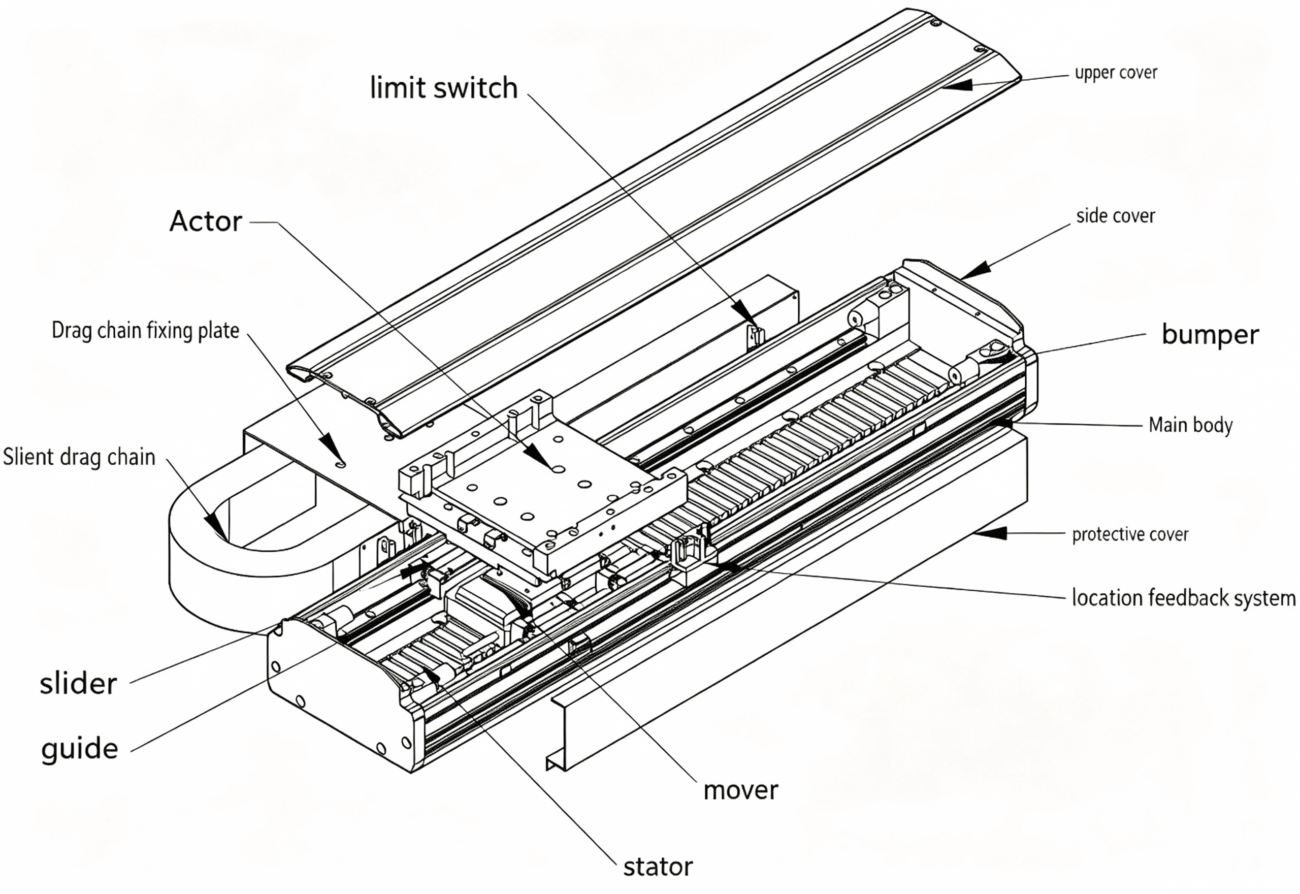
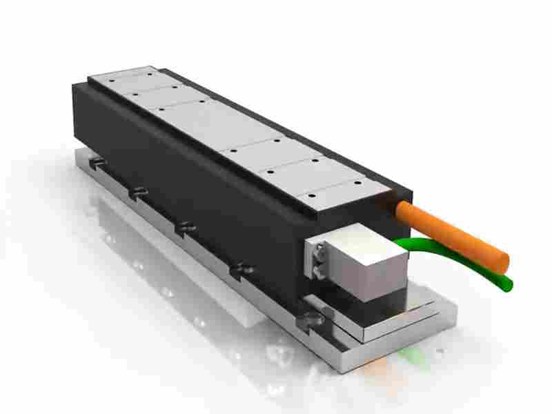
A typical linear motor system includes:
Coil assembly: Generates a controlled electromagnetic field when current flows through the windings.
Permanent magnet track: Provides the magnetic field in permanent-magnet linear motor designs.
Mechanical support structure: Maintains alignment and supports the motor components.
Linear guide system: Controls the movement of the load and helps maintain straight-line travel.
Feedback and motion control: Uses encoders, sensors, a servo drive, and a motion controller to regulate position and speed.
The exact structure depends on the motor design.
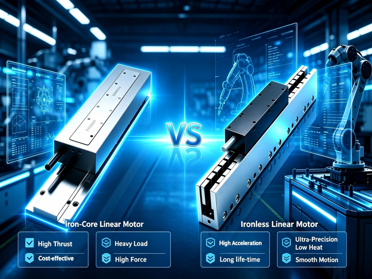
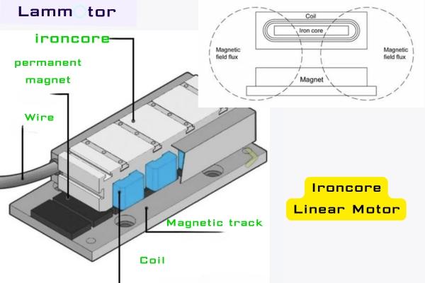
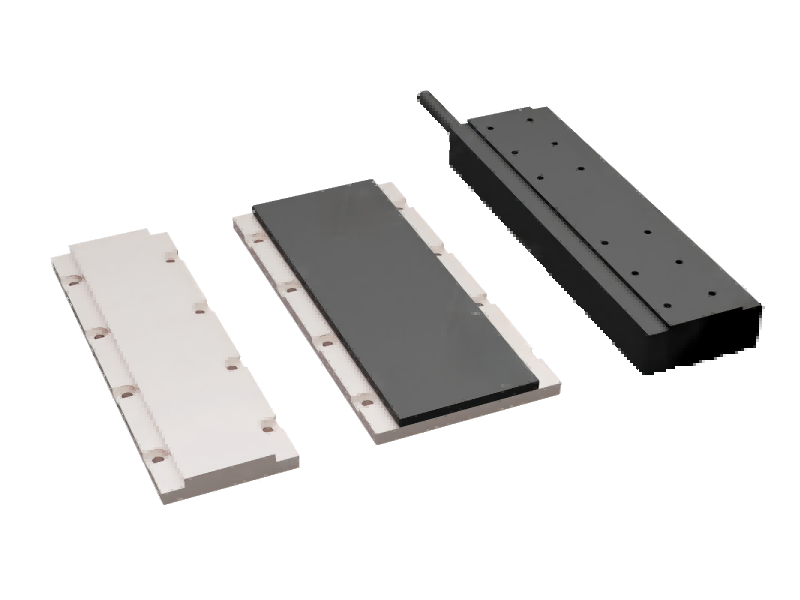
For example, an iron-core linear motor typically uses a laminated iron core to increase magnetic flux and force density. A coreless linear motor eliminates the iron core from the moving coil assembly, reducing moving mass and minimizing certain forms of magnetic attraction and cogging.
Understanding these differences is essential before selecting materials or defining the manufacturing process.
2. Step One: Material Selection and Engineering Design
Every successful linear motor starts with the right design. Before manufacturing begins, engineers need to define the required stroke, thrust, speed, acceleration, positioning accuracy, duty cycle, and installation space.
These requirements determine the motor’s electromagnetic structure and mechanical configuration.
Choosing the right materials
Common materials used in linear motor manufacturing include:
Copper winding wire
Copper provides good electrical conductivity and is widely used for motor coils. Depending on the design, manufacturers may use round magnet wire or rectangular copper wire to achieve the required winding arrangement and copper fill factor.
Laminated electrical steel
Iron-core linear motors commonly use stacked electrical steel laminations. The lamination structure helps reduce eddy-current losses compared with a solid iron core.
Permanent magnets
Neodymium-iron-boron (NdFeB) magnets are widely used in permanent-magnet linear motors because of their high magnetic energy density. Magnet grade, temperature rating, coating, dimensions, and magnetization direction must match the application.
Structural materials
Aluminum alloys are frequently used for motor housings, mounting plates, and supporting structures because they offer a useful balance of weight, stiffness, and machinability. Steel and other materials may be selected where greater rigidity or different thermal characteristics are required.
Insulation and bonding materials
Electrical insulation protects the windings, while suitable adhesives secure permanent magnets and other components. Both must be compatible with the motor’s operating temperature, mechanical loads, and expected service life.
Electromagnetic and mechanical design
Engineers use CAD tools to develop the mechanical structure and electromagnetic simulation tools to evaluate the magnetic circuit, coil arrangement, force characteristics, and thermal behavior.
At this stage, they also determine the nominal air gap, mounting tolerances, cooling method, cable routing, and feedback sensor configuration.
Getting these details right early can reduce rework during assembly and improve the consistency of the finished motor.
3. Step Two: Manufacturing the Stator or Coil Assembly
The coil assembly is one of the most important parts of a linear motor. Its manufacturing process depends on whether the design uses an iron core or a coreless coil structure.
Coil winding
An automatic winding machine or a dedicated winding fixture is used to form the copper wire into the specified coil geometry.
The winding process must maintain consistent wire tension, turn count, coil dimensions, and phase arrangement. Poor winding quality can lead to insulation damage, uneven heat distribution, electrical imbalance, or inconsistent motor performance.
For custom linear motors, the winding design may need to be adapted to the required thrust, available installation space, thermal limits, and motion profile.
Iron-core lamination and assembly
For an iron-core linear motor, electrical steel laminations are punched, cut, or otherwise processed to the required geometry and stacked into the core assembly.
The laminations must be aligned and secured without compromising their electrical insulation. Excessive deformation or damaged insulation can increase magnetic losses and affect performance.
The winding coils are then installed into the designated slots or assembled with the core, depending on the motor design.
Insulation, impregnation, and curing
After winding and electrical connections are completed, the coil assembly may undergo varnish impregnation, vacuum-pressure impregnation, potting, or another suitable insulation process.
The selected process helps secure the windings, improve electrical insulation, and support heat transfer.
Curing temperature and duration must follow the specifications of the insulation system and bonding materials. There is no single temperature-and-time combination that applies to every linear motor.
Electrical inspection
Before moving to final assembly, manufacturers typically check:
Coil continuity and winding resistance
Phase-to-phase resistance balance
Insulation resistance
Dielectric withstand performance, where required
Coil dimensions and visible insulation defects
These checks help identify electrical problems before the motor is integrated with its magnetic track and control system.
The permanent magnet track provides the magnetic field required by many linear motor designs. Its accuracy and consistency have a direct impact on the motor’s force characteristics and running stability.
Magnet preparation and orientation
Permanent magnets are prepared according to the specified dimensions, grade, coating, and magnetization direction.
In many linear motor designs, adjacent magnets are arranged with alternating north and south poles. However, the exact pole sequence depends on the magnetic circuit and motor topology.
Correct magnet orientation is critical. An incorrectly positioned magnet can disturb the intended magnetic field and reduce the consistency of the motor’s thrust.
Precision bonding and mechanical fixing
Magnets are positioned on the magnetic track or back iron using a dedicated fixture. Depending on the design, they may be secured with structural adhesive, mechanical retention, or a combination of methods.
The bonding process requires controlled surface preparation, adhesive application, positioning, and curing.
The adhesive must withstand the expected operating temperature, vibration, and mechanical loads. Magnet coatings and substrate materials must also be compatible with the selected bonding process.
Magnetic inspection
After assembly, manufacturers may use a gaussmeter or a magnetic field measurement system to inspect the magnetic field distribution along the track.
The purpose is to identify unexpected variations, incorrect pole orientation, or discontinuities between magnet sections.
For long-stroke systems, track straightness, mounting surface flatness, and the alignment of adjacent track sections are also important. Poorly aligned sections can cause changes in the effective air gap and lead to unwanted force variation during travel.
5. Step Four: Precision Machining and Mechanical Assembly
Even a well-designed electromagnetic assembly will not deliver its intended performance if the mechanical structure is inaccurate.
Precision machining and controlled assembly help ensure that the motor, magnetic track, linear guide, and feedback components work together as a complete system.
CNC machining of structural components
CNC milling, drilling, grinding, or other precision machining processes may be used to manufacture:
Motor mounting plates
Aluminum housings and support structures
Magnet track bases
Guide rail mounting surfaces
End plates, brackets, and positioning features
Critical dimensions should be defined according to the motor’s actual performance requirements. Flatness, parallelism, straightness, and mounting-hole positions can all affect assembly accuracy.
Tighter tolerances may be necessary for high-precision applications, but they can also increase manufacturing cost. Tolerances should therefore be based on the complete system design rather than selected arbitrarily.
Installing the linear guide system
The linear guide supports the moving load and controls its path. Depending on the application, the system may use profile rail guides, precision linear guides, or another suitable guiding mechanism.
During installation, the guide rail must be aligned with the intended motion axis. Mounting surfaces, fastening torque, carriage preload, and load distribution all influence running smoothness and positioning behavior.
A linear motor provides the driving force, but it does not automatically guarantee straightness or positioning accuracy. Those characteristics depend on the complete mechanical and control system.
Air gap adjustment
The air gap is the clearance between the relevant magnetic and electromagnetic components. Its required value depends on the motor’s construction, electromagnetic design, mechanical tolerances, and operating conditions.
During assembly, technicians use suitable measurement tools, alignment fixtures, and dimensional inspection methods to verify the clearance and its consistency along the travel path.
An excessively large air gap can reduce the available electromagnetic force. An insufficient or uneven gap can increase the risk of interference, particularly when mechanical deflection, thermal expansion, or mounting errors occur.
The objective is not simply to minimize the air gap. It is to maintain the designed clearance consistently and safely throughout the motor’s operating range.
For long-stroke systems, this can require particular attention to guide alignment, track straightness, structural stiffness, and the cumulative tolerances of individual components.
6. Step Five: Integrating Encoders, Sensors, and Motion Control
A linear motor can generate force without a mechanical transmission such as a ball screw, but a precision positioning system still needs appropriate feedback and control.
Linear encoder installation
A linear encoder measures the position of the moving axis. Depending on the application, the system may use an optical or magnetic encoder with an appropriate resolution and accuracy specification.
Encoder installation requires careful attention to mounting alignment, readhead clearance, signal quality, and thermal stability.
Encoder resolution should not be confused with system positioning accuracy. The final result also depends on the mechanical structure, calibration, servo tuning, thermal behavior, and measurement method.
Sensor and cooling integration
Temperature sensors may be installed to monitor critical thermal locations. Depending on the power level and duty cycle, the motor may use natural convection, forced-air cooling, liquid cooling, or another thermal management approach.
Additional components can include limit switches, home sensors, cable carriers, protective covers, and cable management systems.
These details are particularly important in semiconductor equipment, automated inspection machines, precision assembly lines, and other applications that require reliable operation over repeated motion cycles.
Servo drive and control configuration
The motor is connected to a compatible servo drive and motion controller. Engineers configure the commutation method, feedback settings, current limits, acceleration, deceleration, and other control parameters.
The exact setup depends on the motor design, encoder type, drive capabilities, and application requirements.
Proper integration allows the system to deliver controlled acceleration, stable motion, and repeatable positioning under the intended load.
7. Step Six: Linear Motor Testing and Quality Control
A motor should not be considered ready for delivery simply because it moves. Testing must verify that its electrical, mechanical, thermal, and dynamic characteristics meet the agreed specifications.
Electrical testing
Electrical inspection typically includes winding resistance, phase balance, insulation resistance, and other tests required by the design and applicable safety procedures.
The test limits depend on the motor’s rated voltage, insulation system, temperature rating, and relevant standards.
Thrust and force consistency testing
A force measurement setup can be used to evaluate thrust against current and operating conditions.
Depending on the application, testing may examine:
Continuous and peak thrust
Force constant
Force variation along the travel path
Detent force or cogging behavior, where applicable
Performance under the specified current and temperature limits
These measurements help determine whether the motor delivers the expected force consistently.
Positioning accuracy and repeatability
A linear encoder and an independent measurement instrument, such as a laser interferometer where appropriate, can be used to evaluate positioning performance.
Positioning accuracy, repeatability, resolution, and straightness are different measurements. They should be specified and verified separately.
For high-precision applications, the test procedure should define the measurement range, reference conditions, load, temperature, and evaluation method.
Thermal and endurance testing
Thermal tests help confirm that winding and structural temperatures remain within the design limits under the specified duty cycle.
Endurance testing may involve repeated movements, representative loads, acceleration cycles, and extended operating periods. The test duration should reflect the application and the required reliability evidence.
A 200-hour test, for example, may be appropriate for a particular validation plan, but it is not a universal requirement for every linear motor.
The final inspection should document the measured results and confirm whether the motor meets the agreed acceptance criteria.
8. Iron-Core vs. Coreless Linear Motor Manufacturing
Iron-core and coreless linear motors share several manufacturing steps, but their electromagnetic structures and assembly requirements are different.
Manufacturing factor
Iron-core linear motor
Coreless linear motor
Coil structure
Windings assembled with a laminated iron core
Windings formed without an iron core in the coil assembly
Main magnetic structure
Permanent magnet track and iron-core coil assembly in common designs
Permanent magnet track and coreless coil assembly in common designs
Magnetic attraction
Can have significant attraction between the iron core and magnet track
Eliminates the core-related attraction associated with an iron-core coil
Cogging behavior
May require attention to cogging and force ripple
Generally avoids iron-core cogging, although other force variations can remain
Manufacturing focus
Lamination quality, core assembly, winding integration, and magnetic alignment
Coil geometry, winding support, thermal management, and dimensional stability
Typical design priorities
High force density and compact thrust generation
Low moving mass, smooth motion, and reduced core-related magnetic attraction
Neither structure is universally better. The right choice depends on thrust requirements, speed, acceleration, positioning behavior, thermal constraints, machine geometry, and cost.
For a high-load industrial axis, an iron-core design may be appropriate. For applications that prioritize low moving mass and smooth motion, a coreless design may be worth considering.
The decision should be based on the complete motion profile rather than one specification alone.
9. Common Linear Motor Manufacturing Problems and How to Prevent Them
Several manufacturing issues can affect motor performance even when the individual components appear to be within tolerance.
Uneven air gap
Possible causes include inaccurate mounting surfaces, guide misalignment, track straightness errors, or structural deformation.
Prevention: Inspect critical surfaces, establish reliable alignment references, and verify clearance across the operating stroke.
Coil insulation damage
Possible causes include excessive winding tension, sharp edges, poor handling, or an unsuitable impregnation process.
Prevention: Control winding tension, protect wire insulation during assembly, and perform electrical inspections before final integration.
Permanent magnet misalignment
Possible causes include inaccurate fixtures, incorrect pole orientation, adhesive movement during curing, or track assembly errors.
Prevention: Use controlled positioning fixtures, verify magnet orientation, and inspect the completed magnetic track.
Excessive temperature rise
Possible causes include inappropriate current settings, insufficient cooling, high duty cycles, or inadequate thermal design.
Prevention: Evaluate the real motion profile, confirm the continuous and peak operating conditions, and validate the cooling arrangement through testing.
Poor positioning performance
Possible causes include encoder installation errors, mechanical misalignment, unsuitable servo parameters, or thermal drift.
Prevention: Check the complete motion system, calibrate the feedback device where required, and tune the servo under representative operating conditions.
In practice, the most reliable results come from treating electromagnetic design, mechanical assembly, feedback, and motion control as one integrated engineering problem.
10. Why Choose a Custom Linear Motor or Linear Motion System?
Standard linear motors can be suitable for many applications. However, some machines require a specific stroke length, installation envelope, payload, acceleration, positioning performance, or multi-axis configuration that a standard product cannot accommodate.
A custom linear motor solution can address these requirements at the design stage.
When developing a custom system, the engineering team should consider:
Stroke and travel length: The required motion range and available installation space.
Thrust and payload: Continuous force, peak force, moving mass, and external loads.
Speed and acceleration: The actual motion profile, cycle time, and operating frequency.
Positioning requirements: Accuracy, repeatability, resolution, and settling time.
Control compatibility: Encoder interfaces, servo drive selection, and controller integration.
Operating environment: Dust, contamination, temperature, and other application-specific conditions.
HCY Automation: Your Mechatronics Specialist for Custom Linear Motion Solutions
HCY Automation focuses on linear motion and linear motor applications where the mechanical structure and motion performance need to match the machine rather than force the machine to fit a standard configuration.
Depending on project requirements and technical feasibility, customization can be explored around linear motor modules, dual-carrier configurations, stroke length, mounting interfaces, guide systems, feedback options, and integration with the customer’s automation architecture.
For a dual-carrier linear motor module, for example, the design discussion should cover whether the two carriers need independent positioning, how their travel ranges overlap, what payload each carrier supports, and how the control system coordinates their movement.
These details influence the mechanical layout, magnetic track arrangement, encoder configuration, cable management, and achievable cycle time.
The most effective way to begin a custom project is to provide the application requirements, including the target stroke, payload, speed, acceleration, positioning accuracy, installation dimensions, and expected operating cycle.
With these details, HCY Automation can assess the application and discuss a suitable linear motion configuration rather than recommending a motor based on thrust or speed alone.
Looking for a custom linear motor, dual-carrier linear motor module, or integrated linear motion system? Contact HCY Automation to discuss your application requirements and explore a configuration tailored to your equipment.
11. Frequently Asked Questions About Linear Motor Manufacturing
How is a linear motor manufactured?
A typical manufacturing process includes engineering design, material preparation, coil winding, insulation treatment, permanent magnet track assembly where applicable, precision machining, mechanical integration, electrical connection, and performance testing. The exact sequence depends on whether the design is iron-core, coreless, or another linear motor architecture.
What materials are used to make a linear motor?
Common materials include copper winding wire, electrical steel laminations for iron-core designs, permanent magnets such as NdFeB, aluminum or steel structural components, electrical insulation materials, and suitable adhesives. Material selection depends on the motor’s electromagnetic, mechanical, and thermal requirements.
What is the difference between an iron-core and a coreless linear motor?
An iron-core linear motor uses a laminated iron core in its coil assembly, which can provide high force density but may introduce significant magnetic attraction and cogging. A coreless design removes the iron core from the coil assembly, reducing moving mass and core-related cogging. The best option depends on the required thrust, motion quality, and system design.
Why is air gap control important in linear motor assembly?
The air gap affects electromagnetic coupling and available thrust. An excessively large gap can reduce force, while an insufficient or uneven gap can increase the risk of interference and inconsistent operation. The correct clearance must follow the motor design and remain controlled throughout the operating stroke.
How is linear motor performance tested?
Testing may include winding resistance, insulation checks, thrust measurement, force variation, temperature rise, positioning accuracy, repeatability, and endurance under representative operating conditions. The specific tests and acceptance limits should be defined according to the application and motor specifications.
Can a linear motor be customized for a specific machine?
Yes. A linear motor or complete linear motion system can be designed or configured around application-specific requirements such as stroke, payload, thrust, speed, acceleration, mounting dimensions, feedback, and control compatibility. The available customization options depend on the supplier’s engineering capabilities and the project requirements.
How do I choose a linear motor manufacturer?
Look beyond maximum thrust and top speed. Evaluate the manufacturer’s ability to understand your motion profile, recommend a suitable motor architecture, integrate the guide and feedback systems, meet your installation requirements, and verify performance through appropriate testing. Engineering support and clear acceptance criteria are especially important for custom equipment.
Conclusion: Precision Manufacturing Makes the Difference
Manufacturing a linear motor is not just a matter of winding copper wire and installing permanent magnets. It requires coordinated control of electromagnetic design, material quality, coil insulation, mechanical tolerances, air gap, thermal behavior, and motion control.
Each stage contributes to the finished system’s thrust, efficiency, smoothness, positioning performance, and long-term reliability.
For machine builders and automation engineers, the key is to select a motor architecture and manufacturing approach that match the real application.
Whether you need a standard linear motor, a custom linear motor module, a dual-carrier configuration, or a complete linear motion solution, a well-defined engineering process is the starting point for reliable performance.
**Have a linear motion application that requires a tailored solution? Contact HCY Automation to discuss your design requirements, integration needs
Linear Motion & Motion Control | Precision Positioning | Industrial Automation Solutions | HCY Automation
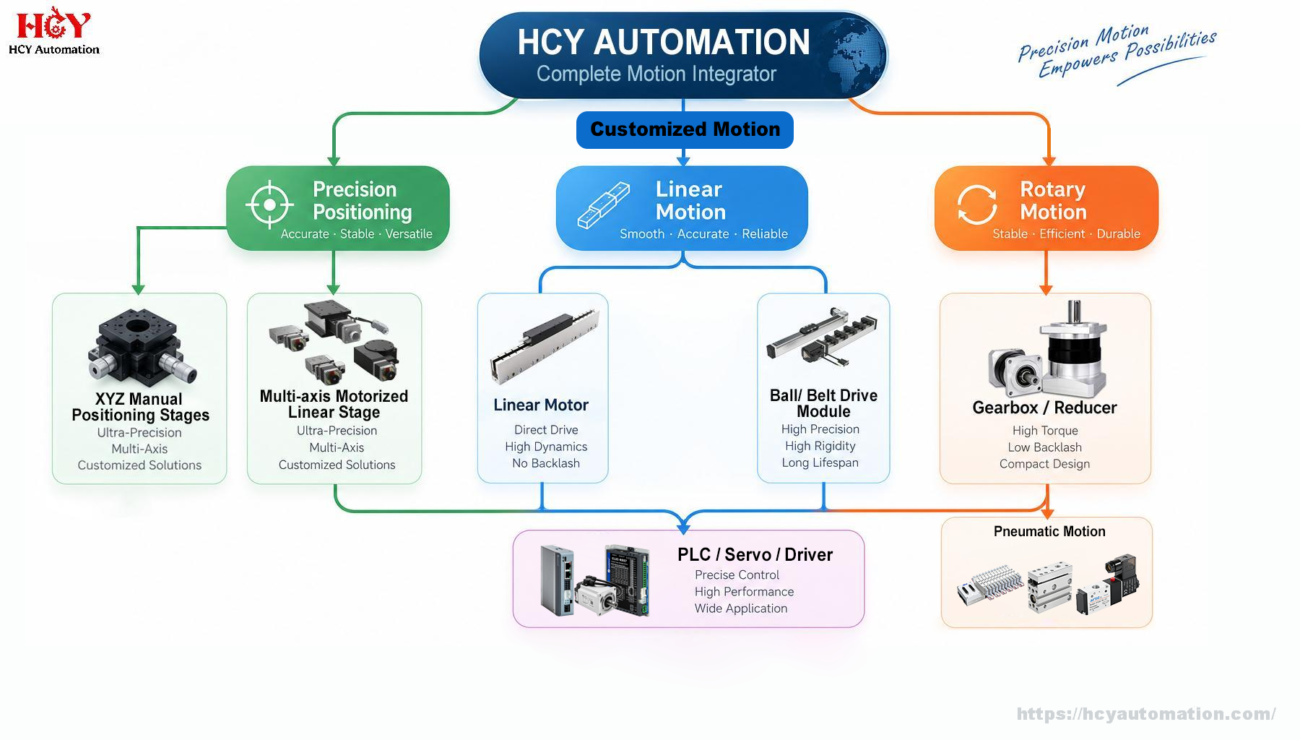
HCY Automation delivers integrated solutions across motion control, linear motion, robotics, machine vision, pneumatic systems, and precision gearboxes to help global manufacturers build smarter, faster, and more reliable production lines. Our engineering team helps you select and integrate the right motion control, robotics, and automation components for your specific application.