Linear Motor vs. Rotary Motor: Key Differences, Pros, Cons & Applications
Compare linear motors vs. rotary motors in positioning accuracy, speed, acceleration, load capacity, maintenance, and cost. Find the right drive for your automation system. Choosing between a linear motor and a rotary motor can have a direct impact on the speed, positioning accuracy, mechanical design, and overall cost of an automation system.
Both convert electrical energy into mechanical motion, but they deliver that motion in different ways. A rotary motor produces rotational movement, while a linear motor generates force directly along a straight path.
For applications involving precision positioning, high-speed transfer, semiconductor handling, or multi-axis automation, understanding these differences helps engineers select a drive system that meets both performance requirements and budget constraints.
In this guide, HCY Automation compares linear motors and rotary motors in terms of operating principles, positioning accuracy, speed, acceleration, load capacity, maintenance, and total cost of ownership.
1. What Is a Linear Motor?
A linear motor is an electric motor designed to produce linear motion directly, without requiring a rotary-to-linear transmission mechanism such as a ball screw, timing belt, or gear rack.
Its operating principle is similar to that of a rotary motor, but the electromagnetic structure is arranged to produce force along a straight axis rather than torque around a rotating shaft.
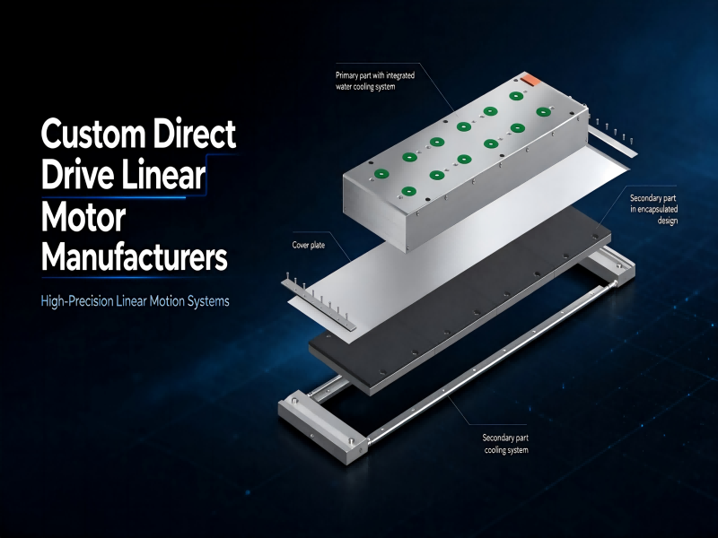
In a typical linear motor system, the electromagnetic interaction between the primary and secondary components generates thrust. Depending on the design, the motor may use an iron-core or coreless structure.
A complete linear motion system may also include linear guides, an encoder, a servo drive, a motion controller, and a supporting mechanical structure. These components work together to control position, velocity, and acceleration.
Key advantages of linear motors
Direct drive: Eliminates the need for a separate rotary-to-linear transmission mechanism.
High dynamic response: Supports rapid acceleration, deceleration, and frequent changes in motion.
High positioning potential: Can achieve precise positioning when paired with suitable feedback, controls, and mechanical guidance.
High-speed operation: Suitable for applications requiring fast, repeated linear movement.
Reduced transmission wear: Avoids wear in mechanical transmission components such as ball screws and belts.
Potential limitations
Higher initial system cost in many configurations.
Heat management may be important, particularly in high-force or continuous-duty applications.
Accurate alignment, mounting, feedback integration, and servo tuning require careful engineering.
The motor itself does not determine the system’s load capacity; the guides, carriage, frame, and mounting structure must also support the application.
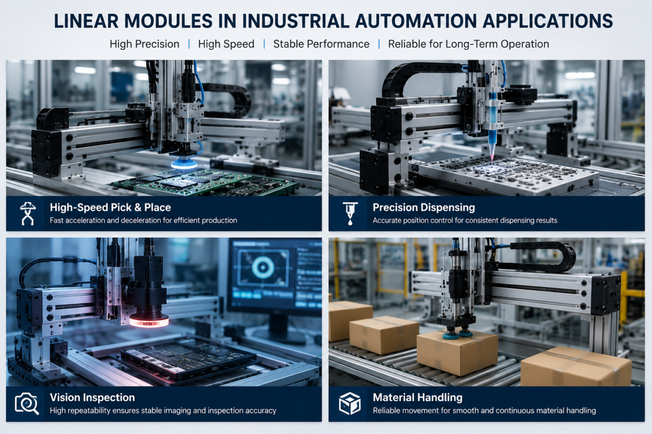
Linear motors are commonly considered for semiconductor equipment, precision inspection, electronic assembly, high-speed pick-and-place systems, and other applications requiring fast and accurate linear movement.
2. What Is a Rotary Motor?
A rotary motor converts electrical energy into rotational mechanical motion. It is one of the most widely used drive technologies in industrial automation.
Common types include AC servo motors, stepper motors, induction motors, and DC motors. Each has different characteristics in terms of control, torque, speed, cost, and application suitability.
When a rotary motor is used to create linear movement, a transmission mechanism is typically added. Depending on the application, this may be a ball screw, timing belt, gear rack, or another mechanical drive.
For example, a servo motor connected to a ball screw rotates the screw, causing the nut and attached carriage to move along a linear guide. A belt-driven system uses pulleys and a timing belt to move the carriage.
Key advantages of rotary motors
Broad product selection: Different motor types are available for a wide range of torque, speed, and control requirements.
Flexible mechanical design: Can drive rotary equipment directly or be integrated with linear transmission mechanisms.
Cost-effective options: Mature motor technologies and standardized components can help control initial system cost.
Suitable for varied loads: With appropriate motor sizing, gearing, and mechanical design, rotary systems can handle a wide range of applications.
Easy system integration: Widely used in conveyors, pumps, packaging machinery, machine tools, robotic equipment, and general automation systems.
Ball screws, belts, gears, and couplings introduce their own maintenance requirements and performance limitations.
Backlash, compliance, friction, and transmission errors may affect positioning performance, depending on the mechanism.
Maximum speed and acceleration depend on the motor, transmission design, load, and operating conditions.
Rotary motors remain an effective choice for many industrial applications, particularly when the required motion, accuracy, and production rate can be achieved with a conventional mechanical transmission.
3. Linear Motor vs. Rotary Motor: Key Differences
The most important distinction is how each system generates and transmits motion.
A linear motor produces linear thrust directly. A rotary motor produces torque and typically requires an additional mechanism when linear travel is needed.
Comparison factor
Linear motor drive
Rotary motor with linear transmission
Motion generation
Direct linear thrust
Rotary motion converted to linear movement
Mechanical transmission
No rotary-to-linear transmission required
Usually uses a ball screw, belt, rack, or similar mechanism
Positioning accuracy
High potential with suitable feedback and mechanics
Can also achieve high accuracy with a properly designed system
Speed and acceleration
Well suited to high dynamic performance
Depends on motor and transmission limitations
Backlash
No transmission backlash from a screw or belt mechanism
Depends on transmission type and mechanical design
Load capacity
Determined by motor thrust and supporting mechanics
Determined by motor torque, transmission, guides, and structure
Maintenance
Fewer transmission wear components
May require inspection or maintenance of transmission components
Initial investment
Often higher for a complete precision system
Often more economical for standard applications
Typical applications
High-speed precision positioning and advanced automation
Conveyors, general automation, linear modules, and conventional machinery
Important: These are general tendencies, not universal rules. A well-designed ball screw system can deliver excellent positioning accuracy and high load capacity, while a linear motor system still requires appropriate mechanical guidance, feedback, and thermal management.
4. Positioning Accuracy: Which Is Better?
Positioning accuracy is often one of the first factors engineers consider when comparing linear motor and rotary motor systems.
A linear motor eliminates the mechanical transmission between a rotary motor and the linear load. This can reduce transmission-related errors and improve dynamic response. With a suitable linear encoder, precision guide system, and properly tuned servo controller, a linear motor can support demanding positioning requirements.
However, a linear motor is not automatically more accurate than every rotary motor system.
A precision ball screw driven by a servo motor can also achieve excellent positioning performance. Actual results depend on screw lead and accuracy, encoder resolution, mechanical stiffness, thermal expansion, backlash, assembly quality, and control settings.
When evaluating a system, distinguish between three specifications:
Positioning accuracy: How closely the actual position matches the commanded position.
Repeatability: How consistently the system returns to the same position under defined conditions.
Resolution: The smallest position change that the control and feedback system can distinguish.
These specifications are related, but they are not interchangeable.
For semiconductor equipment, optical inspection, precision dispensing, and electronic assembly, engineers should evaluate the complete motion system rather than compare motor types alone.
5. Speed and Acceleration: Where Linear Motors Have an Advantage
Linear motors are particularly attractive when an application requires high speed, rapid acceleration, frequent starts and stops, or fast changes in travel direction.
Because they eliminate the need for a rotary-to-linear transmission, they avoid certain mechanical limitations associated with ball screws and belts. This can be valuable in high-throughput equipment where cycle time directly affects production capacity.
Rotary motor systems can also achieve high speeds. However, a ball screw may be limited by factors such as screw length, critical speed, vibration, and mechanical stiffness. Belt-driven systems have different limits related to belt tension, pulley design, load, and positioning requirements.
The correct comparison is therefore between complete drive systems under the same operating conditions.
A linear motor may be worth considering when:
Cycle time is a major production constraint.
The carriage must accelerate and decelerate rapidly.
The machine performs frequent, repetitive high-speed positioning.
High dynamic performance must be maintained over a demanding duty cycle.
For moderate-speed transfer, standard positioning, and cost-sensitive equipment, a rotary servo motor with a suitable linear module may offer a better balance of performance and cost.
6. Load Capacity and Mechanical Design
A common misconception is that a linear motor is unsuitable for heavy loads or that a rotary motor always provides greater thrust.
In practice, load capacity depends on the complete system design.
For a linear motor system, engineers need to consider continuous and peak thrust, moving mass, acceleration, duty cycle, guide rail capacity, carriage moment loads, mounting stiffness, and heat dissipation.
For a rotary motor system, the relevant factors include motor torque, transmission ratio, ball screw or belt specifications, bearing capacity, guide rail ratings, and the mechanical structure.
A ball screw-driven linear module may be an effective choice for applications requiring substantial axial force, rigid positioning, or a compact standardized assembly. A linear motor can also support demanding loads when the motor and mechanical structure are appropriately selected.
Vertical installation requires additional attention. The system must safely support the load against gravity and account for power loss, braking requirements, and the possibility of unintended movement.
The best solution is the one that meets the load, stiffness, safety, and motion requirements with an appropriate engineering margin.
7. Maintenance, Noise, and Service Life
Linear motors eliminate several mechanical transmission components, which can reduce the maintenance associated with those components. There is no ball screw nut or drive belt in the motor’s force-generation path.
However, a linear motor system is not maintenance-free. Linear guides, bearings, cable management, cooling components where applicable, and other mechanical elements still require attention. Encoder cleanliness, alignment, and control-system condition can also affect long-term performance.
Rotary motor systems have different maintenance needs depending on their transmission mechanism.
Ball screw systems: May require lubrication and inspection of the screw, nut, bearings, and guide rails.
Belt-driven systems: May require belt tension checks, belt condition inspections, and pulley maintenance.
Direct-drive linear motor systems: Avoid screw or belt transmission maintenance but still require inspection of guides, cables, feedback devices, and mounting conditions.
Noise also depends on the whole machine. Eliminating a screw or belt transmission may reduce certain mechanical noise sources, but guide movement, cooling fans, structural resonance, and other equipment can still produce noise.
Service life should be evaluated using duty cycle, load, speed, lubrication, contamination, temperature, installation quality, and manufacturer specifications—not motor type alone.
8. Initial Cost vs. Total Cost of Ownership
A rotary motor combined with a standard ball screw or belt-driven linear module is often a practical starting point for cost-sensitive automation projects. Standard components are widely available, and many applications can be served without a customized direct-drive system.
A linear motor system may require a larger initial investment in the motor, servo drive, feedback system, cooling arrangements where needed, and precision mechanical integration.
That does not mean the linear motor solution will always cost more over its entire service life.
In high-throughput applications, improved cycle time, fewer transmission-related maintenance tasks, and reduced mechanical wear may help offset the initial investment. The actual payback depends on production volume, machine utilization, maintenance costs, and the value of increased output.
When comparing solutions, include:
Motor, drive, and feedback hardware.
Linear guides, frame, and mounting components.
Installation, alignment, and commissioning.
Controller integration and tuning.
Routine maintenance and replacement parts.
Production downtime and expected service life.
Cycle time and output requirements.
A lower purchase price is not necessarily the lowest total cost of ownership. Equally, a higher-performance drive is not worth the additional cost if the application cannot benefit from its capabilities.
9. Which Drive System Is Right for Your Application?
The following guide can help narrow down the options during the initial design stage.
Application requirement
Solution worth evaluating
Why
High-speed precision positioning
Linear motor
Direct drive can support high dynamic performance
Semiconductor and optical inspection
Linear motor or precision servo axis
The choice depends on accuracy, vibration, travel, and budget
Standard pick-and-place automation
Belt or ball screw linear module
Mature, practical solutions for many motion profiles
Long-stroke, high-speed transfer
Belt-driven module or linear motor
Compare speed, travel, payload, and positioning requirements
High axial force with controlled linear travel
Ball screw-driven module or suitably sized linear motor
Select according to thrust, stiffness, and duty cycle
General conveyor and rotary machinery
Rotary motor
Direct rotary motion is often the simplest approach
Cost-sensitive standard equipment
Rotary servo with a standard linear module
Standard components can simplify sourcing and integration
High-throughput multi-axis equipment
Linear motor or a combination of drive technologies
Evaluate cycle time, synchronization, and total system cost
These are starting points rather than fixed rules. A final selection should be based on the actual motion profile, payload, stroke, positioning tolerance, installation space, and budget.
10. How to Select the Right Motion System
Before choosing a linear motor or a rotary motor with a transmission mechanism, define the application requirements clearly.
Step 1: Specify the motion profile.
Determine travel distance, target speed, acceleration, deceleration, cycle time, and how frequently the axis changes direction.
Step 2: Calculate the load.
Include the workpiece, fixture, carriage, cables, and any other moving components. Consider gravity, friction, and external forces.
Step 3: Define positioning requirements.
Specify positioning accuracy, repeatability, resolution, and settling time separately. Avoid selecting a system based on resolution alone.
Step 4: Evaluate the installation environment.
Consider available space, mounting orientation, contamination, temperature, vibration, cable routing, and cooling requirements.
Step 5: Compare the complete system cost.
Include the motor, drive, transmission, guides, controller, commissioning, maintenance, and expected production performance.
Step 6: Validate the design.
Confirm the selected system against the required duty cycle and safety conditions. Where necessary, conduct a motion test under representative load and operating conditions.
Frequently Asked Questions
1. Is a linear motor better than a rotary motor?
Neither technology is universally better. A linear motor can be advantageous for high-speed, high-acceleration, precision linear motion. A rotary motor is often a practical and economical choice for rotary machinery and many conventional linear axes.
2. Can a rotary motor achieve high positioning accuracy?
Yes. A rotary servo motor combined with a precision ball screw, suitable encoder, rigid mechanical structure, and well-tuned controller can achieve high positioning accuracy. The actual result depends on the complete system.
3. Why are linear motor systems often more expensive?
The total system may require a linear motor, servo drive, feedback devices, precision guides, and careful thermal and mechanical integration. The cost difference varies with specifications, system architecture, and production volume.
4. Do linear motors require less maintenance?
They eliminate screw or belt transmission components, reducing the maintenance associated with those parts. However, the guides, bearings, feedback devices, cables, and other system components still require appropriate inspection and maintenance.
5. Are linear motors suitable for long-stroke applications?
Yes, they can be used in long-stroke systems. The design must account for the required thrust, thermal behavior, guide alignment, encoder arrangement, mounting structure, and overall cost. A belt-driven module may be more economical for some long-travel applications.
6. What is the difference between a linear motor and a linear module?
A linear motor is the electromagnetic drive that generates linear thrust. A linear module is a mechanical motion assembly that may use a ball screw, timing belt, or linear motor, together with guides, a carriage, and supporting components. The terms describe different parts of a motion system and should not be treated as interchangeable.
Conclusion: Choose Based on the Application, Not Just the Motor
Linear motors and rotary motors serve different motion requirements, and both remain important technologies in industrial automation.
A linear motor is worth evaluating when high dynamic performance, direct linear drive, and reduced transmission complexity are priorities. A rotary motor with a ball screw or belt-driven linear module may be the better choice when standardization, load requirements, straightforward integration, and cost are more important.
At HCY Automation, we look at the complete motion requirement—not just the motor specification. By considering speed, positioning accuracy, load, stroke, installation conditions, and total cost, engineers can identify a drive solution that fits the machine and its production goals.
Need help selecting a linear motor, servo motor, or linear module for your automation project? Contact HCY Automation to discuss your application and motion requirements.
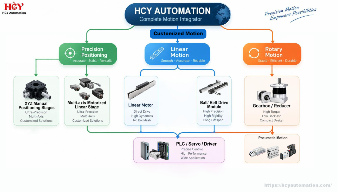
HCY Automation delivers integrated solutions across motion control, linear motion, robotics, machine vision, pneumatic systems, and precision gearboxes to help global manufacturers build smarter, faster, and more reliable production lines. Our engineering team helps you select and integrate the right motion control, robotics, and automation components for your specific application.