Motion Control Components: The Complete Guide to Servo Motors, Stepper Motors, PLCs, and Encoders in 2026
The Nervous System of Modern Manufacturing
Every industrial robot that welds a car body. Every CNC machine that mills a turbine blade. Every automated conveyor that sorts packages at 600 units per hour. They all share one invisible architecture: a motion control system that translates digital commands into precise mechanical movement.
The global servo motor and drive marketreached USD 16.8 billion in 2025 and is accelerating toward USD 32.4 billion by 2034 at 7.6% CAGR. The motion control card market is growing at 5.8% CAGR, driven by demand for multi-axis synchronization and real-time control. The encoder market — the feedback layer that closes the control loop — is expanding at 6.2% CAGR, fueled by the shift from incremental to absolute multi-turn encoders in robotics and semiconductor equipment.
But for machine builders and system integrators, these numbers are secondary to a more immediate problem: How do I choose the right motion control components for my application?
This guide is the definitive resource for understanding, selecting, and integrating the four pillars of industrial motion control: servo motors, stepper motors, PLC controllers, and encoders.
The Four Pillars of Motion Control
Pillar 1: Servo Motors — Precision with Feedback
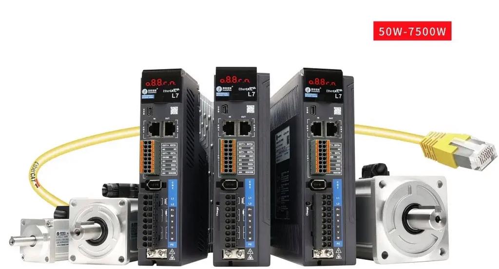
A servo motor is a rotary actuator that uses closed-loop feedback to maintain precise control over position, velocity, and torque. Unlike standard AC motors that run at fixed speeds, servo motors adjust their output in real time based on commands from a motion controller and feedback from an encoder.
Why servo motors dominate precision automation:
Closed-loop control: The encoder tells the drive exactly where the motor shaft is. If position drifts, the controller corrects it within milliseconds.
High dynamic response: Servo motors can accelerate from 0 to 3,000 rpm in < 50 ms, making them ideal for high-speed pick-and-place and robotic joints.
Full torque at zero speed: Unlike induction motors, servos deliver rated torque even when stationary — critical for holding a vertical axis against gravity.
Wide speed range: Typical servo motors operate smoothly from 1 rpm to 6,000 rpm with consistent performance.
Simple open-loop positioning with low speed and no precision requirements
Cost-sensitive applications where stepper motors suffice
Environments with extreme electrical noise that interferes with encoder signals
Pillar 2: Stepper Motors — Simplicity with Open-Loop Control
A stepper motor is a brushless DC motor that divides a full rotation into a fixed number of steps — typically 200 steps per revolution (1.8° per step). By energizing coils in sequence, the motor moves in discrete increments without requiring position feedback.
Why stepper motors remain indispensable:
No encoder required: Open-loop control simplifies wiring, reduces cost, and eliminates feedback failure modes.
High holding torque: Stepper motors generate maximum torque at zero speed, making them excellent for holding loads without power consumption (when using detent torque).
** deterministic positioning:** Each pulse equals a known mechanical displacement — no cumulative error between moves.
Low cost: A complete stepper motor + driver kit typically costs 30–50% less than an equivalent servo system.
The microstepping revolution: Modern stepper drivers use microstepping — dividing each full step into 16, 32, 64, or even 256 microsteps. This achieves:
Pillar 3: PLC and Motion Control Cards — The Brain of the System
A PLC (Programmable Logic Controller) is the industrial computer that executes the automation program — reading inputs, processing logic, and commanding outputs. In motion control applications, the PLC (or a dedicated motion control card) generates the position/velocity profiles that tell the motor drives what to do and when.
Interpolation: Coordinates movement across multiple axes simultaneously — essential for CNC contouring and robot path planning.
Electronic gearing: Synchronizes a slave axis to a master axis at a programmable ratio — used in packaging film feed and printing registration.
Electronic camming: Replaces mechanical cams with software profiles — enabling infinite cam shapes without physical changeover.
When to choose PLC-based motion:
The application requires I/O integration (sensors, valves, HMI) alongside motion
The machine uses 3–8 axes of coordinated motion
The system must comply with IEC 61131-3 programming standards
Pillar 4: Encoders — The Eyes of the Control Loop An encoder is a sensor that converts mechanical position into electrical signals. It is the feedback device that closes the loop in servo systems and provides position verification in stepper systems.
Two fundamental types:
Type
How It Works
Best For
Key Advantage
Incremental encoder
Outputs pulses (A/B quadrature) as the shaft rotates
General automation, cost-sensitive applications
Low cost; simple interface; high resolution
Absolute encoder
Outputs a unique digital code for every position within one or multiple revolutions
Robotics, CNC, safety-critical applications
No homing required; position retained after power loss; multi-turn capability
Resolution matters:
A 2,500 PPR (pulses per revolution) incremental encoder with 4× quadrature decoding delivers 10,000 counts per revolution.
A 23-bit absolute encoder delivers 8,388,608 positions per revolution — enough to detect 0.00004° of shaft rotation.
Why absolute encoders are taking over: The absolute encoder market is growing faster than incremental, driven by:
Safety requirements: Functional safety standards (SIL 3, PL e) demand position verification at power-up without homing.
Efficiency: No homing cycle means faster machine startup and higher OEE.
Battery-free multi-turn: Modern magnetic and capacitive absolute encoders track multiple revolutions without a backup battery — eliminating maintenance and environmental concerns.
How the Four Pillars Work Together: A Real-World Example
Consider a 3-axis CNC milling machine:
The PLC / motion control card reads the G-code program and calculates the interpolated path for X, Y, and Z axes.
The motion card sends position commands to three servo drives at 1 kHz update rate.
Each servo drive commands its servo motor to accelerate, cruise, and decelerate along the path segment.
Each servo motor’s absolute encoder reports actual position back to the drive at 20-bit resolution.
The drive’s control loop compares commanded position vs. actual position every 62.5 microseconds and adjusts current to eliminate error.
The PLC monitors spindle speed, coolant flow, and emergency stops via digital I/O — coordinating motion with the broader machine process.
Result: A complex 3D contour machined to ±0.01 mm accuracy at 5 m/min feed rate.
How to Select Motion Control Components: The Decision Matrix
Application Requirement
Servo Motor
Stepper Motor
PLC + Motion Card
Encoder Type
Positioning accuracy < 0.05 mm
✅ Required
❌ Insufficient
✅ Required
✅ Absolute
Positioning accuracy 0.1–1 mm
✅ Excellent
✅ Adequate
⚠️ Optional
✅ Incremental
Speed > 1,000 rpm
✅ Excellent
❌ Poor
✅ Required
✅ Incremental
Speed < 500 rpm
✅ Good
✅ Excellent
⚠️ Optional
✅ Incremental
Dynamic load changes
✅ Excellent
❌ Risk of stall
✅ Required
✅ Absolute
Cost-sensitive (< $500/axis)
❌ Expensive
✅ Excellent
✅ Basic PLC
❌ Optional
Multi-axis synchronization
✅ Excellent
❌ Poor
✅ Required
✅ Absolute
Safety-critical / no homing
✅ Excellent
❌ Unsuitable
✅ Required
✅ Absolute multi-turn
Integration Best Practices: 5 Rules That Prevent Field Failures
Rule 1: Match the Encoder to the Drive Protocol
A BiSS-C encoder will not communicate with a drive expecting SSI or EnDat 2.2. Verify protocol compatibility before purchase. When in doubt, choose encoders and drives from the same manufacturer or explicitly listed as compatible.
Rule 2: Size the Drive for Peak Current, Not Just Continuous
Servo drives are rated by continuous current and peak current. A motor that runs within continuous torque may demand 3× peak current during emergency stops. Size the drive for peak, or it will fault under stress.
Rule 3: Cable Length Matters for Encoders
Incremental encoder signals degrade over long cable runs due to capacitance and noise. For runs > 10 meters, use differential line driver outputs (RS-422) or switch to a serial absolute encoder (BiSS, EnDat, SSI) that is inherently noise-immune.
Rule 4: PLC Scan Time Must Be Faster Than Mechanical Response
If your PLC scan time is 10 ms but your mechanical system settles in 5 ms, the PLC is effectively blind during critical motion phases. For high-performance motion, use a dedicated motion control card with 1 ms or faster update cycles.
Rule 5: Grounding and Shielding Are Non-Negotiable
Servo drives switch at 10–20 kHz, generating electrical noise that can disrupt encoder signals, PLC communications, and HMI touchscreens. Use star grounding topology, shielded twisted-pair cables, and ferrite cores on encoder and communication lines.
Frequently Asked Questions (FAQ)
What is the difference between a servo motor and a stepper motor?
A servo motor uses closed-loop feedback from an encoder to maintain precise position and velocity control, with high dynamic response and full torque across a wide speed range. A stepper motor operates in open-loop mode, moving in discrete steps without feedback, offering lower cost and simpler control but limited speed and vulnerability to stall under load variation.
When should I choose a stepper motor over a servo motor?
Choose a stepper motor when: positioning accuracy is > 0.1 mm, speed is < 1,000 rpm, the load is constant and predictable, and cost is a primary constraint. Choose a servo motor when: accuracy is < 0.1 mm, speed is > 1,000 rpm, the load varies dynamically, or multi-axis synchronization is required.
What does a motion control card do that a standard PLC cannot?
A motion control card performs real-time trajectory generation, multi-axis interpolation, and high-speed position loop closure — typically at 1–4 kHz update rates. Standard PLCs execute ladder logic at 10–100 ms scan times, which is too slow for coordinated servo motion. The motion card handles the “fast” control loop; the PLC handles the “slow” logic and I/O.
What is the difference between incremental and absolute encoders?
An incremental encoder outputs pulses as the shaft rotates and requires a homing reference position at power-up. An absolute encoder outputs a unique digital code for each position and retains position information after power loss — no homing required. Absolute encoders are essential for safety-critical applications and large machines where homing is time-consuming.
How do I calculate the required encoder resolution?
Divide the required positioning accuracy by the mechanical travel per motor revolution. Example: A ball screw with 10 mm pitch requires ±0.01 mm accuracy. The motor must resolve 0.01 / 10 = 0.001 rev = 0.36°. An encoder with 1,000 PPR (0.36° per pulse) is the minimum; 2,500 PPR (0.144°) provides margin.
Can I use a servo motor without an encoder?
Technically yes (in sensorless vector mode), but not for positioning applications. Sensorless control estimates rotor position from current and voltage waveforms, but accuracy is insufficient for automation. For positioning, an encoder is mandatory.
What communication protocols connect encoders to servo drives?
Common protocols include: Incremental (A/B/Z quadrature) — universal, simple; SSI (Synchronous Serial Interface) — point-to-point, robust; BiSS-C — open standard, high speed, bidirectional; EnDat 2.2 — Heidenhain proprietary, high performance; HIPERFACE DSL — SICK proprietary, single-cable solution. Verify drive compatibility before selecting an encoder protocol.
How do I prevent encoder signal loss in noisy environments?
Use differential signaling (RS-422) for incremental encoders. Choose serial absolute encoders (BiSS, EnDat) which are inherently noise-immune. Keep encoder cables separated from power cables by > 100 mm. Use shielded twisted-pair cables with the shield grounded at the drive end only. Add ferrite cores on both ends of the encoder cable.
What is electronic gearing in motion control?
Electronic gearing synchronizes a slave axis to a master axis at a programmable ratio — for example, making a conveyor track a rotary knife at exactly 3.5:1 speed ratio. This replaces mechanical gearboxes and chains, enabling infinite ratio adjustment via software and eliminating mechanical wear.
What is the typical lifespan of a servo motor and encoder?
A properly sized and maintained servo motor can operate for 20,000–50,000 hours before bearing replacement. Modern optical encoders last > 50,000 hours; magnetic encoders are even more durable with no LED degradation. The most common failure mode is cable fatigue at the flex point — not the motor or encoder itself.
Bottom Line: Motion Control Is Integration, Not Isolation
The best servo motor in the world is useless with a mismatched encoder. The most advanced motion control card is wasted on a stepper motor that stalls under load. The most precise encoder is irrelevant if the PLC scan time is too slow to respond.
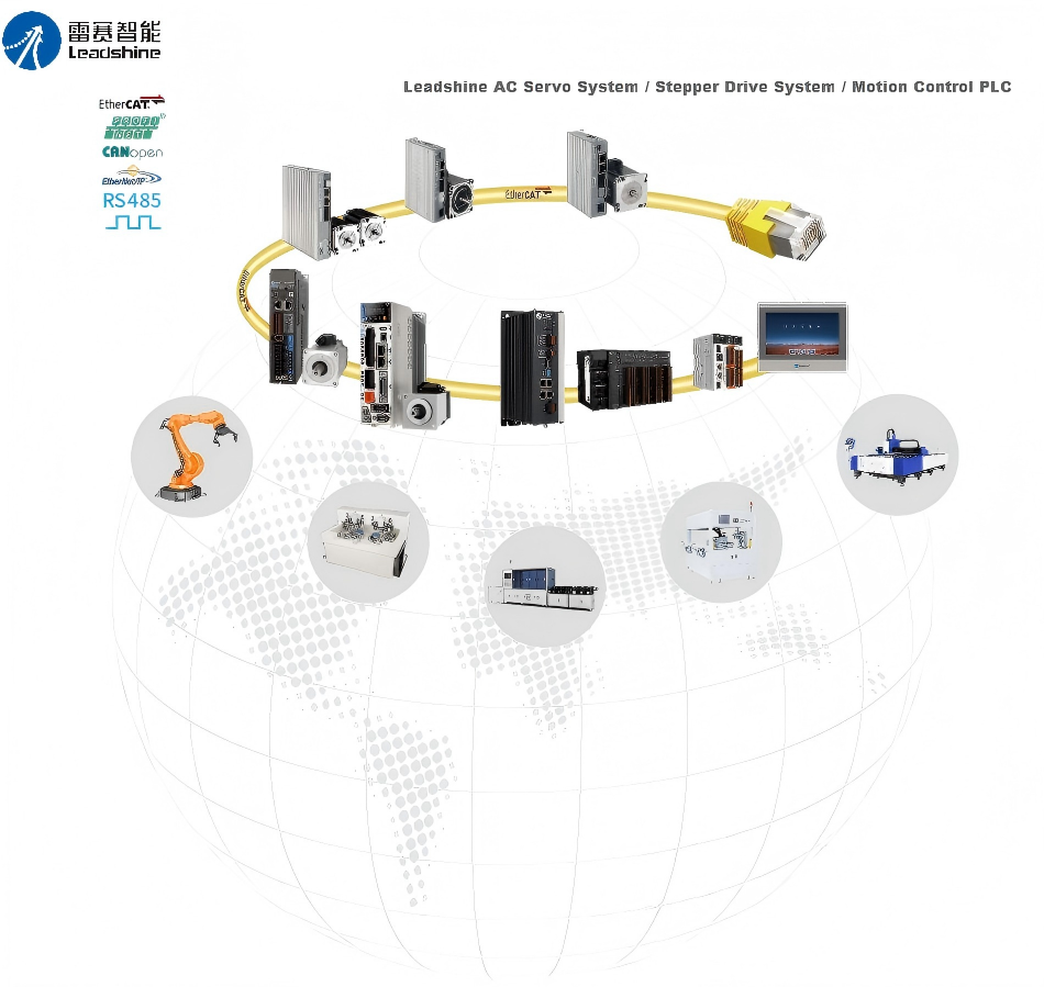
Motion control is an integration problem. The four pillars — servo motors, stepper motors, PLCs/motion cards, and encoders — must be selected as a coordinated system, not as individual components.
In 2026, as the industrial automation market accelerates toward $32.4 billion, the machine builders who master this integration will build the factories, robots, and medical devices that define the next decade.
Related Reading:
[How to Size a Servo Planetary Gearbox: The Complete Engineer’s Guide]
HCY Automation delivers integrated solutions across motion control, linear motion, robotics, machine vision, pneumatic systems, and precision gearboxes to help global manufacturers build smarter, faster, and more reliable production lines. Our engineering team helps you select and integrate the right motion control, robotics, and automation components for your specific application.