Vertical vs. Horizontal Linear Module Installation: Load Capacity and Safety Factors
Choosing a linear module for vertical installation? The load capacity that works perfectly for a horizontal axis may not be sufficient for a vertical Z-axis. Gravity, acceleration, motor torque, brake capacity, and load distribution all affect the final selection.
For engineers designing automated assembly lines, pick-and-place systems, inspection equipment, and precision handling machines, understanding these differences is essential to preventing unexpected downtime, positioning errors, and load drops.
In this guide, HCY Automation explains how vertical and horizontal linear modules differ, how to calculate the required driving force, how to determine an appropriate load safety margin, and what to check before selecting a linear motion system.
1. Vertical vs. Horizontal Linear Modules: What Is the Difference?
The main difference is the direction of gravity relative to the direction of motion.
In a horizontal linear module, gravity acts perpendicular to the travel direction. The drive system mainly needs to overcome acceleration forces, friction, cable drag, and any external process resistance.
In a vertical linear module, gravity acts along the travel direction. The drive must continuously support the moving assembly against gravity while also meeting the required speed and acceleration.
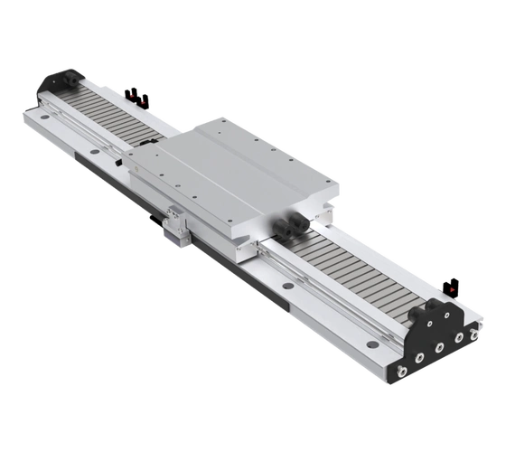
1. Industrial Linear Module for Horizontal Installation
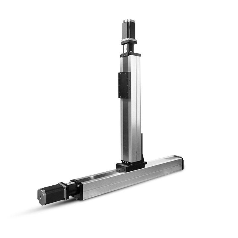
2. Vertical Z-Axis Ball Screw Linear Actuator with Servo Motor
Comparison
Horizontal installation
Vertical installation
Gravity direction
Perpendicular to travel
Along the travel axis
Main drive requirement
Acceleration and resistance
Gravity, acceleration, and resistance
Motor sizing
Based on motion profile and external loads
Must account for lifting and controlled lowering
Load distribution
Primarily supported by the guide system
Depends on guide orientation, load offset, and moments
Power-off behavior
Usually no gravity-driven movement along the axis
Potential uncontrolled downward movement
Additional safety measures
Application-dependent
Brake and/or suitable anti-fall protection
Key selection concern
Payload, speed, accuracy, and service life
Payload, lifting force, brake capacity, and load retention
One important distinction: vertical installation does not automatically mean that the guide rail has a lower rated load capacity. The allowable load depends on the guide orientation, bearing arrangement, moment ratings, mounting structure, and manufacturer specifications.
The difference is that the drive system must overcome gravity, and the entire assembly must be checked under the actual vertical operating conditions.
2. Why Does a Vertical Linear Module Need a Different Load Safety Factor?
A common selection mistake is to choose a linear module based only on the payload listed in the catalog.
The actual moving mass includes more than the workpiece. It also includes the gripper, fixture, mounting plate, sensors, cables, and any other components moving with the carriage.
For vertical applications, the design must account for both the total moving mass and the forces generated during operation.
Gravity is a constant load
The gravitational force is calculated as:
F_g = m × g

Where:

- F_g = Gravitational force (N)
- m = Total moving mass (kg)
- g = Gravitational acceleration, approximately 9.81 m/s²

For a vertical axis with a total moving mass of 20 kg:

F_g = 20 × 9.81 = 196.2 N
The drive system must account for approximately 196.2 N of downward gravitational force before considering acceleration, friction, transmission losses, or external process forces.
A horizontal axis with the same moving mass does not need to continuously generate lifting force simply to maintain its position along the horizontal travel direction.
Acceleration increases the required driving force
When a vertical axis accelerates upward, the drive must overcome both gravity and inertia.
A simplified equation is:
F_up = m × (g + a) + F_r

Where:

- a = Upward acceleration (m/s²)
- F_r = Combined resistance from friction and other relevant forces (N)

For example, if the moving mass is 20 kg, upward acceleration is 1.5 m/s², and estimated resistance is 20 N:

F_up = 20 × (9.81 + 1.5) + 20

F_up = 246.2 N
For example, if the moving mass is 20 kg, upward acceleration is 1.5 m/s², and estimated resistance is 20 N:
[ F_{\text{up}}=20(9.81+1.5)+20 ]
[ F_{\text{up}}=246.2\text{ N} ]
This is the estimated required upward force before applying a design margin.
The actual selection must also consider the transmission efficiency, motor torque-speed characteristics, duty cycle, peak loads, and the manufacturer’s allowable thrust.
Is there a universal safety factor for vertical linear modules?
No. There is no single safety factor that applies to every linear module, drive mechanism, and operating condition.
A design margin should be determined from the manufacturer’s selection method and the application’s load uncertainty, acceleration, shock loads, duty cycle, service-life requirements, and consequences of failure.
A higher safety factor alone does not guarantee a safe vertical axis. Brake capacity, guide loading, screw or belt strength, mounting rigidity, and power-loss behavior must be checked independently.
3. How to Select a Load Safety Factor for Vertical and Horizontal Installation
The following table is a practical engineering reference, not a set of universal industry-mandated values.
Selection consideration
Horizontal axis
Vertical axis
Moving mass
Include the complete moving assembly
Include the complete moving assembly
Driving force
Calculate acceleration and resistance
Include gravity in the force calculation
Dynamic loads
Check acceleration, deceleration, and emergency stops
Check lifting, lowering, and braking in both directions
Load moments
Check center-of-gravity offsets and external forces
Check gravity-induced and dynamic moments
Safety margin
Based on load uncertainty and operating conditions
Based on load uncertainty, gravity, dynamic loads, and failure consequences
Power-off protection
Depends on the application
Verify load retention and anti-fall requirements
For preliminary engineering, a designer may evaluate different candidate safety margins, such as 1.5 or 2.0, where appropriate to the component rating and the manufacturer’s guidance. These figures are calculation examples, not automatic recommendations for every vertical axis.
The important rule is to apply the safety factor to the correct quantity. A factor applied to required motor thrust is not automatically a valid factor for guide-block capacity, screw life, belt tension, or brake holding torque.
These components have different rating methods and failure modes.
4. How to Calculate the Required Load for a Vertical Linear Module
A reliable selection starts with the real operating conditions rather than the nominal payload alone.
Step 1: Calculate the total moving mass
Include:
Workpiece or product
Gripper and tooling
Moving carriage and mounting plate
Sensors, brackets, and other moving accessories
Cables and hoses carried by the axis
For example, a 12 kg workpiece, 4 kg fixture, and 4 kg moving carriage give a total moving mass of 20 kg.
Step 2: Calculate the Required Driving Force
For upward acceleration, the required driving force can be estimated using the following formula:
F_up = m × (g + a) + F_r
Where:
F_up = Required upward driving force (N)
m = Total moving mass (kg)
g = Gravitational acceleration (9.81 m/s²)
a = Upward acceleration (m/s²)
F_r = Friction and other resistance forces (N)
Example:
Assume the total moving mass is 20 kg, the upward acceleration is 1.5 m/s², and the estimated resistance force is 20 N.
F_up = 20 × (9.81 + 1.5) + 20
F_up = 246.2 N
If a design factor of 1.5 is appropriate for the selected component and application, the design force is:
F_design = 246.2 × 1.5
F_design = 369.3 N
Note: The design factor of 1.5 is an illustrative example, not a universal industry standard. Always verify the manufacturer’s load ratings, motor torque, transmission efficiency, and safety requirements before selecting a vertical linear module.
Where:
Note: The design factor of 1.5 is an illustrative example, not a universal industry standard. Always verify the manufacturer’s load ratings, motor torque, transmission efficiency, and safety requirements before selecting a vertical linear module.
This is an illustrative design-force target. It does not replace checking the manufacturer’s rated thrust, allowable load, peak torque, service life, and operating limits.
Step 3: Check downward motion
Do not size a vertical axis only for lifting.
During downward travel, gravity may assist the motion. The servo system may need to control the descent and absorb regenerated energy rather than simply provide driving torque.
Downward deceleration also requires attention because the drive must control the moving load against gravity. Review the complete motion profile, including emergency-stop conditions.
Step 4: Check load moments and guide capacity
The position of the payload matters as much as its mass.
A long gripper or an offset fixture can create substantial pitch, roll, or yaw moments. These forces may overload a guide system even when the total payload appears acceptable.
Check the manufacturer’s allowable moment ratings and combined-load calculation method. Also verify the mounting plate, fasteners, module body, and supporting frame.
5. Vertical Linear Actuator Brake Selection: How to Prevent Load Drops
Power-loss protection is one of the most important considerations for a vertical linear module.
When the servo drive loses power, gravity can pull the carriage downward if the transmission and holding system do not prevent movement. This may damage workpieces, tooling, or surrounding equipment.
Check the brake holding torque
For a screw-driven or belt-driven vertical axis, the brake must be evaluated against the torque transmitted by the suspended load.
This is an idealized calculation. Actual brake sizing must account for transmission efficiency, the brake’s location in the drive train, dynamic conditions, engagement time, and the manufacturer’s rating method.
For belt-driven systems, pulley radius and transmission efficiency must also be considered when converting linear force into torque.
What type of brake should be used?
A spring-applied, electrically released holding brake is commonly used for vertical servo axes. It engages when electrical power is removed, subject to the brake’s operating specifications.
However, a standard motor holding brake should not automatically be treated as a dynamic emergency brake. In many systems, the servo first performs a controlled stop before the brake engages.
Depending on the risk assessment, additional protection may be required, such as a mechanical anti-fall device, counterbalance mechanism, or mechanical stop.
HCY Automation recommendation: Before approving a vertical axis, verify the load-retention method under power loss, emergency stop, and maintenance conditions. Do not rely solely on the motor’s rated torque or a nominal brake specification.
6. Common Mistakes When Selecting Vertical Linear Modules
Mistake 1: Using horizontal load capacity for a vertical axis
A module that meets the payload requirement in a horizontal installation may not provide enough lifting force or holding capability when mounted vertically.
How to avoid it: Recalculate the drive force, torque, guide moments, and holding requirements for the actual mounting orientation.
Mistake 2: Calculating only the workpiece weight
Ignoring fixtures, grippers, brackets, and moving accessories underestimates the real load.
How to avoid it: Calculate the complete moving mass and include any additional process forces.
Mistake 3: Selecting the motor without checking the brake
A motor may provide sufficient torque during normal operation but still fail to retain the load safely when power is removed.
How to avoid it: Verify the brake’s holding capacity and engagement behavior separately from the motor’s running performance.
Mistake 4: Ignoring acceleration and deceleration
A vertical axis may operate smoothly at constant speed but experience excessive torque or unstable motion during rapid starts and stops.
How to avoid it: Calculate the full motion profile and verify both upward and downward operation.
Mistake 5: Overlooking center-of-gravity offsets
An extended fixture or an off-center payload can create large moments on the guide blocks.
How to avoid it: Provide the load dimensions and center-of-gravity position during the selection process.
Mistake 6: Assuming a larger safety factor solves every problem
Increasing a calculated force margin does not correct a poorly aligned mounting surface, an undersized brake, excessive deflection, or an unsuitable transmission.
How to avoid it: Check each component against its own rating and the applicable manufacturer selection procedure.
7. Which Linear Module Is Best for Vertical Installation?
The right solution depends on stroke length, speed, precision, payload, and the required safety architecture.
Linear module type
Typical strengths
Key vertical-axis considerations
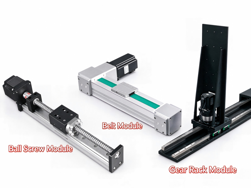
Ball screw linear module
High positioning accuracy and stiffness
Screw lead, critical speed, drive torque, backdriving, and brake requirements
Belt-driven linear module
Long strokes and high-speed transport
Belt tension, pulley torque, load retention, and dynamic performance
Linear motor module
Direct drive, fast response, and high dynamic performance
Continuous force, heat dissipation, servo control, and power-off load retention
A ball screw module is often suitable for precision Z-axis positioning. A belt-driven module can be a good choice for longer-stroke handling applications when its load and safety requirements are satisfied. A linear motor module is attractive for demanding dynamic performance, but vertical use requires particular attention to continuous force and load retention.
No drive type is automatically the best choice for every vertical application. The final selection should follow the required motion profile, operating environment, accuracy, lifetime, and risk assessment.
8. HCY Automation’s Practical Checklist for Linear Module Selection
Before choosing a vertical or horizontal linear module, confirm the following:
Total moving mass, including tooling and accessories
Installation orientation and available mounting space
Required stroke, maximum speed, and acceleration
Positioning accuracy and repeatability requirements
Center-of-gravity position and applied moments
Required driving force and motor torque
Transmission capacity and expected service life
Brake holding capacity and power-loss behavior for vertical axes
Emergency-stop behavior and anti-fall protection where required
Mounting rigidity, alignment, and maintenance requirements
Providing these details early helps engineers avoid unnecessary oversizing, repeated commissioning, and costly changes after the equipment has been assembled.
Conclusion: Calculate the Real Load Before Selecting a Linear Module
The main difference between vertical and horizontal linear modules is not simply the mounting direction. It is how gravity, acceleration, load distribution, and power-off behavior affect the complete motion system.
For horizontal axes, selection focuses on moving mass, acceleration, external resistance, guide loading, and positioning requirements. For vertical axes, gravity must also be included in the drive calculation, and the brake and load-retention system must be evaluated independently.
At HCY Automation, we recommend selecting linear modules according to the actual operating conditions rather than relying on a single catalog load figure. A well-matched linear motion system can help improve positioning stability, reduce unnecessary maintenance, and support reliable automated production.
Need help selecting a linear module for your application? Contact HCY Automation with your payload, stroke, speed, acceleration, installation orientation, and precision requirements. Our team can help evaluate the appropriate linear motion solution for your equipment.
HCY Automation delivers integrated solutions across motion control, linear motion, robotics, machine vision, pneumatic systems, and precision gearboxes to help global manufacturers build smarter, faster, and more reliable production lines. Our engineering team helps you select and integrate the right motion control, robotics, and automation components for your specific application.