Industrial automation has revolutionized modern manufacturing operations. Whether it’s a robotic arm depositing electronic components on a high-speed production line or a CNC machine carving out complex metal parts with micron-level precision, there’s one technology that powers these precision-driven processes: the servo motor. The move towards Industry 4.0 and smart manufacturing means that understanding how a servo motor works is now essential knowledge for engineers, system integrators and procurement professionals alike.
The global servo motors market continues to grow at a rapid pace driven by demand from semiconductor fabrication, medical devices, packaging machinery and renewable energy sectors. Unlike conventional electric motors that just spin when powered, a servo motor provides controlled and accurate motion with instant feedback – something that is essential when precision in positioning, speed control and dynamic response are crucial. However, with the prevalence of these devices, many professionals struggle to understand the inner workings that make servo motors different from other motion control technologies.
A servo motor is an electromechanical device that converts electrical signals to precise mechanical motion in a closed loop. The position, speed or torque that is commanded is constantly compared with the actual feedback from an integrated sensor, usually an encoder, and the servo drive adjusts the output of the motor in real time to eliminate any deviation. This feedback loop corrects errors, so servo motors can position very accurately (to fractions of an arc-minute), provide consistent torque over their entire speed range and react to dynamic load changes within milliseconds.
This article provides a comprehensive technical overview of how a servo motor works, describing the basic components and control theory, and commercial selection criteria for industrial applications. If you’re selecting servo motors and drives for a new automation project, troubleshooting an existing motion system, or just expanding your engineering knowledge, the following sections will give you a complete understanding of how servo motors work. We will look at encoders and their function, electromagnetic brakes and how they work, AC vs DC vs micro servo motors and the important relationship between servo drives and precision positioning.
What Is a Servo Motor?
A servo motor is an electromechanical device. It is used for precise control of angular or linear position, velocity and acceleration . It consists of a motor coupled to a feedback sensor . It is controlled by a servo drive which uses closed-loop control algorithms to hold the output state at the desired value despite load changes .
In simple terms , a servo motor does not rotate when voltage is applied . It “knows” precisely its location, where it is to go and how fast it must get there. This intelligence is the result of the feedback loop which distinguishes servo systems from open loop systems. The answer is this continuous cycle of command, measurement, comparison, correction when an engineer asks “how does a servo motor work simple”.
The main difference between a servo motor and a normal electric motor is the closed loop control. A typical AC induction motor or DC motor will run at a speed that depends on the voltage applied and the load. If the load increases the motor slows down There is no inherent mechanism to compensate A servo motor, on the other hand, senses the slow down via the encoder, sends the error to the servo drive and the drive immediately applies more current to get back to the target speed. This feedback loop is repeated hundreds, or thousands, of times a second.
The closed-loop servo control concept was developed in the mid 20th century for military and aerospace applications requiring precise positioning of radar antennas and gun turrets. The same principles are at work today in everything from industrial robotic arms to the autofocus mechanisms that make smartphone cameras work, albeit at vastly different scales and cost points.
Basic Components of a Servo Motor System
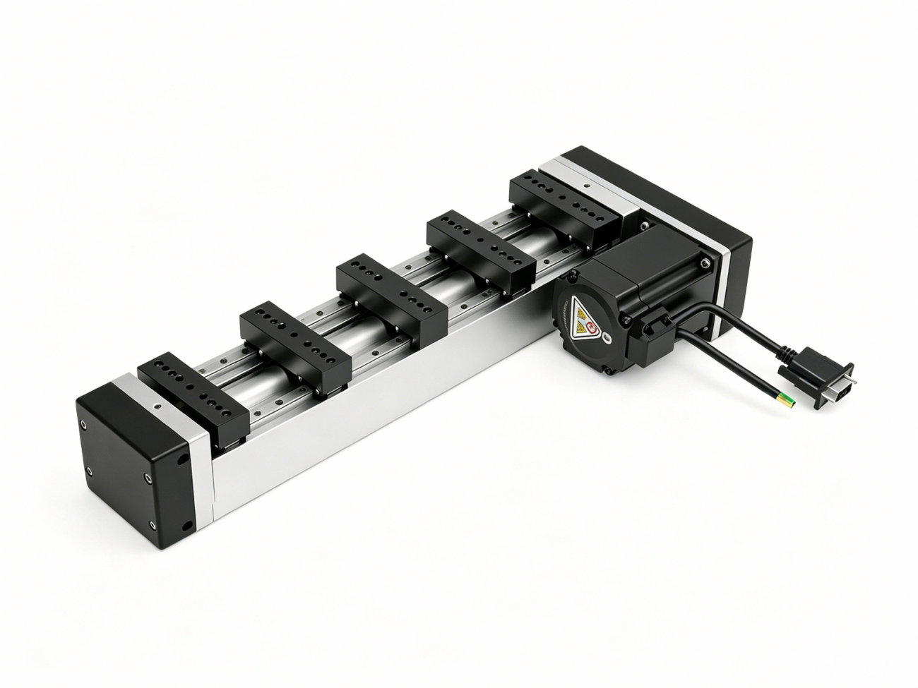
A complete servo motor system consists of four basic elements: the motor (which produces mechanical torque), a feedback sensor (e.g., encoder or resolver, which provides real-time position and speed data), a servo drive (which interprets control commands and supplies controlled electrical power), and a mechanical transmission (which connects the motor to the load, frequently with gear reductions).
To understand how does a servo motor work at the system level it is important to understand each component. The following table explains the function of each component:
Component
Main Function
Important Specifications
Motor (AC or DC)
Converts electrical energy into rotational mechanical energy
The motor itself can be an AC synchronous motor (most common in industrial applications), a brushless DC motor (BLDC) or a brushed DC motor (in smaller, lower cost designs). AC servo motors are extensively used in industrial automation because of high power density, good thermal properties and maintenance free operation. These motors typically have permanent magnets on the rotor and three-phase windings on the stator. The drive carries out electronic commutation based on feedback of the rotor position.
The servo drive is the brains of the system. The device receives control signals from a higher-level controller such as a PLC or motion controller, and converts them to accurately timed current waveforms that are supplied to the motor windings. In the modern servo drives advanced algorithms are implemented, for example field-oriented control (FOC) that allows controlling the independent torque producing and flux producing current components, leading to an optimum efficiency and dynamic response. The drive also monitors critical parameters such as motor temperature, bus voltage and current draw, and will initiate protective shutdowns if any parameter exceeds safe limits.
The mechanical transmission part is usually neglected but very important. In many applications the motor output has to be adjusted by servo gearboxes to meet the load requirements. Planetary gear reducers, harmonic drives and right angle gearboxes all have unique trade-offs in torque multiplication, backlash, stiffness and physical envelope size.
What is a Servo Motor? Principle of Closed-Loop Control
The servo motor works in a three-stage closed-loop cycle. The cycle consists of: the controller sends a command (position, speed, or torque); the feedback sensor measures the actual state of the motor; and the servo drive calculates the difference between the command and the actual state, and then supplies the current to the motor to minimize the error to near zero. This cycle repeats at frequencies usually between 2 and 16 kHz, allowing for real-time dynamic correction.
Let’s consider a practical example to understand how a servo motor works at the most basic level. Suppose a pick-and-place robot needs to move its end effector exactly 300 mm along a linear axis. The motion controller sends a position command to the servo drive which is interpreted as a target encoder count. The drive energizes the motor windings in sequence to produce torque and accelerate the load. As the motor is rotating , the encoder continuously sends the actual position back to the drive .
At any moment in time, the drive determines:
Error = Desired Position – Actual Position
This position error is fed into a PID control algorithm (Proportional-Integral-Derivative). Each term makes a different contribution :
Proportional (P): gives an output proportional to the current error. The larger the error, the stronger the corrective response, so immediate reaction is possible.
Integral (I): The accumulation of the error over time. This is used to negate a steady state offset that the proportional term cannot do alone. This term makes sure the motor gets to the exact target position.
Derivative (D): Responds to the error’s rate of change, adding damping to reduce overshoot and oscillation in rapid movements.
The drive sums the three terms and produces the appropriate phase currents by means of vector control mathematics. The currents are given to the motor through high frequency PWM ( Pulse Width Modulation ) switching. The entire cycle of calculation and correction takes microseconds.
When the motor approaches the end position, the drive reduces the current to slow down smoothly. The integral term continues to refine until the position error is within the acceptable tracking error window. Now the motor is holding position with a small holding current , waiting for the next command to respond instantly .
The closed-loop nature is a direct contrast to open-loop stepper motor systems. The biggest difference between servo vs stepper motors is that steppers assume that every step you tell them to do, they did, while servos constantly monitor and correct themselves. That makes servo motors naturally more reliable in applications where losing steps due to overload or resonance would cause positioning errors that are unacceptable.
How do Servo Motor Encoders Work?
The servo motor encoder works by converting the mechanical rotation into electrical signals which are interpreted by the servo drive as position and speed information. Optical encoders use a patterned disk and photodetectors to generate pulse trains , and magnetic encoders sense changes in magnetic fields from a rotating magnet . The encoder resolution , usually given in pulses per revolution or bits , is directly related to the minimum movement that the servo system can detect .
The encoder is arguably the most important part of answering “how does a servo motor encoder work,” because it provides the feedback that makes closed-loop control possible. Without the encoder, the drive has no means to verify if the motor shaft has actually moved as commanded.
Optical Encoders
The most common type of optical incremental encoders used in industrial servo motors. Their contents are:
A glass or metal disc with radial lines etched into its surface at equal distances
one side of the disk using an LED light source
photodetectors on the other side of the
The disk rotates with the motor shaft and the etchings alternately block and pass light to the photodetectors and give a series of electrical pulses. The encoder produces two channels ( A and B ) in quadrature , i.e. 90 electrical degrees apart , so the drive can determine speed ( from pulse frequency ) and direction ( which channel is leading ) .
High-end servo encoders also have a Z-channel index pulse which fires once per revolution, giving an absolute reference point for homing routines. Typical industrial servo encoders range from 2,500 pulses per revolution up to over 4,000,000 pulses per revolution after interpolation.
Absolute Encoders
In contrast, incremental encoders must be “homed” on power loss. Absolute encoders return a unique code for each possible angular position. They use either multiple tracks on the encoder disk (each track representing one bit of the position word) or magnetic sensing with a non-volatile memory that holds the position even when power is off. Modern absolute encoders use digital protocols such as BiSS-C, EnDat or HIPERFACE to transmit multi-turn position data, temperature and diagnostic information via a serial interface.
Resolutors
Resolvers are another feedback technology that performs well in harsh environments with extreme temperatures, shock and vibration. A resolver is a rotary transformer, it applies an AC excitation signal to a primary winding on the rotor and measures the induced voltages in two secondary stator windings disposed 90° mechanically apart. The ratio of these induced voltages is a function of the rotor angle. Resolvers have lower raw resolution than optical encoders, but their ruggedness makes them preferred in heavy industrial and military applications.
The performance of the servo system depends on the encoder resolution. Higher resolution encoder enables the drive to detect smaller errors in position and respond more precisely , but requires higher frequency processing and can be sensitive to electrical noise . System designers have to weigh up resolution against cost, cable length restrictions and environmental conditions.
What is a Servo Motor Brake
Servo motor brake An electromagnetic safety device which is automatically engaged when power is removed from the brake coil. Under normal power conditions, the electromagnetic coil creates a magnetic field that compresses a spring and releases the brake disc. The motor shaft is free to turn. When power is removed – either purposely with a stop command, or unexpectedly in an emergency – the spring forces the brake disc against a friction surface, locking the shaft and holding the load in place.
It is important to know how a servo motor brake works in applications with vertical axes or with safety-critical machinery, because unexpected movement can result in damage to equipment or personal injury. The electromagnetic brake is a mechanical holding device, as opposed to the dynamic braking servo drives do electrically (dissipating regenerative energy through braking resistors).
Servo Motor Brakes Have the Following Key Features:
Spring engaged, electrically released: In the event of an unexpected power failure, this fail-safe design automatically engages the brake.
Servo motor brakes are to hold a stationary load, not to stop a rotating load. Holding only, not dynamic braking. Repeated dynamic stops with the brake lead to rapid wear of the friction surfaces.
Backlash-free hub design Good servo brakes have a serrated hub or diaphragm coupling that transmits torque without angular play so the position held is exactly what the encoder reads.
Zero-backlash armature plate The friction disc is designed to engage and release without any angular displacement.
The control sequence is carefully choreographed in a normal servo axis with a vertical load ( like a Z axis on a cnc machine ) . If the machine asks for a stop, the servo drive slows the motor down to zero speed and then goes into position hold mode. The controller will not de-energize the brake coil until it is sure the motor has stopped and the spring is able to engage. This sequence does not allow the brake to absorb the kinetic energy and ensures that the load is already in the correct position before the brake locks.
The reverse sequence is used at startup: the servo drive energizes the motor to hold position against gravity then releases the brake and only when it detects that the brake is released does it begin executing motion commands. This coordinated brake control avoids the load from dropping momentarily when the brake unlocks.
The selection of the brake is based on matching the static holding torque to the maximum static load torque with a suitable safety factor (usually 1.5× to 2×). Also important for safety calculations is the brake response time, which is the delay between de-energizing the coil and full torque engagement, as the load may drift slightly in this window.
Types of Servo Motors: AC, DC and Micro Servo Motors
There are three general types of servo motors : AC servo motors ( powered by AC current, usually three-phase, and the most prevalent type in industrial applications ), DC servo motors ( powered by DC voltage, often used in smaller or older applications ), and micro servo motors ( small, low-power servo motors used in hobbyist, educational and light automation applications ) . They all operate on the same closed loop principle but they differ greatly in power density, complexity of control, cost and location of use.
AC Servo Motors
AC servo motors are the most popular choice for industrial automation. These are usually permanent magnet synchronous motors (PMSM) driven by three-phase sinusoidal currents generated by the servo drive. They have rare-earth magnets glued to the rotor and three-phase windings in the stator. They have high torque/inertia ratios and are excellent at thermal dissipation.
The main advantage of AC servo motors is that they can operate over a wide range of speeds. The modern AC servo system provides rated torque from zero to rated speed (usually 3000 RPM) and useful torque to 5000-6000 RPM. The power ratings available range from 50W up to more than 55kW, covering all from small pick-and-place actuators to large injection moulding machines.
DC Servo Motors
The construction of the DC servo motors is a brushed DC motor with permanent magnet stators and wound rotors. The servo drive provides variable DC voltage (through PWM) to control speed and direction. Brushed DC servos are simpler and historically cheaper than AC servos, but they have fallen out of favor in industry due to the wear of the brushes, lower maximum speeds, electromagnetic interference due to commutation, and the need for periodic maintenance. They are still common in older machines , in education , and in some price-sensitive consumer uses .
DC Brushless Servo Motor (BLDC)
In between the two are brushless DC servo motors, which have permanent magnet rotors and electronically commutated stator windings. This is a similar architecture to AC servo motors. The distinction is mostly semantic, and is related to the shape of the back-EMF wave: BLDC motors are more likely to produce trapezoidal back-EMF and are driven with six-step commutation; AC servos are more likely to produce sinusoidal back-EMF and use sinusoidal commutation for smoother torque.
Micro Servo Motor
When it comes to how does a micro servo motor work , the functioning principle is like that of bigger servo motors but at a much smaller scale. Often used in radio controlled models, small robotic joints and consumer electronics, micro servo motors combine the motor, gear train, feedback potentiometer and control electronics into a compact package that is often less than 30mm in any dimension.
How do micro servo motors function in practical use? A pulse-width modulated signal (usually 500-2500 µs pulse width at 50 Hz) commands the desired angular position. A simple comparator circuit drives the small DC motor forward or reverse until the feedback voltage equals the command. The internal potentiometer measures actual position . The gear train multiplies the tiny motor’s torque but reduces speed and output range (typically 0-180 degrees). Micro servos are a good way to get started on the basics of closed loop motion control . They are not good for industrial loads .
The distinctive features are as follows in the comparison table:
Feature
AC Servo Motor
DC Servo Motor (Brushed)
Micro Servo Motor
Power Range
50W – 55kW+
10W – 2kW
<1W – 20W
Speed Range
0 – 6000 RPM
0 – 3000 RPM
0 – 100 RPM (after gearing)
Feedback Type
Optical encoder / resolver
Encoder / tacho
Potentiometer
Control Complexity
High (FOC, vector control)
Medium
Low (PWM comparison)
Typical lifespan
20,000+ hours
3,000 – 5,000 hours (brush limited)
500 – 2,000 hours
Major Applications
CNC, Robotics, Packaging, semiconductor
Legacy machinery, education
Hobby RC, small robots, consumer electronics
What is the Role of the Servo Drive in Motion Control?
The servo drive acts as the intelligent power stage between the motion controller and the motor. It receives high level commands through industrial communication protocols, runs real-time control algorithm calculations and delivers precisely modulated electrical power to the motor windings. The motor cannot do closed loop control without the servo drive.
Modern servo drives have evolved far beyond mere power amplifiers. They now hold:
Multi-axis synchronization: With deterministic fieldbus protocols like EtherCAT or PROFINET IRT, several servo drives synchronize motion between axes in the microsecond range.
Auto-tuning algorithms: The drive automatically detects the inertia of the mechanical system, the resonance frequencies and the friction characteristics and calculates the optimal control gains without manual intervention.
Vibration suppression: Notch filters and adaptive control strategies compensate for mechanical resonance in the coupled load, allowing for higher bandwidth without exciting structural vibrations.
Safety functions: Integrated STO (Safe Torque Off), SS1 (Safe Stop 1) and SLS (Safely Limited Speed) functions meet the requirements for machinery safety without external safety relays.
Special attention has to be paid on the communication interface between the motion controller and the servo drive. Digital fieldbuses have largely superseded traditional analog command interfaces (±10V for speed or torque reference). Pulse-and-direction inputs are still common on lower-cost or stand-alone axes. However, network-based control provides numerous benefits, including reduced wiring, better noise immunity, remote diagnostics, and the ability to change control parameters without physically accessing the drive.
When evaluating a servo system for a particular application, engineers should consider the drive’s control bandwidth, which is the frequency at which the closed-loop response drops by 3 dB. Higher bandwidth provides better disturbance rejection and tracking accuracy but requires a mechanically stiff system, to avoid exciting resonances. Industrial servo drives typically achieve bandwidths of 2 to 4 kHz for current, 200 to 500 Hz for speed and 50 to 200 Hz for position.
How Does a DC Servo Motor operate?
A DC servo motor controls speed and direction by varying the voltage applied to the armature winding. The servo drive uses PWM (pulse width modulation) to provide an adjustable effective voltage, and a feedback device (usually an encoder or tachometer) provides real time speed and position data. The drive compares the feedback to the commanded value and continuously adjusts the PWM duty cycle to minimize the error.
In more detail, a brushed DC servo motor includes:
Permanent magnet stator. Creates a magnetic field for the rotor to rotate through.
Wound rotor (armature) Copper windings on a laminated iron core, attached to the commutator.
Commutator and brushes . Mechanical switching that reverses the direction of current in the rotor windings as they rotate so that torque is in the same direction .
Feedback device: Optical encoder mounted on shaft provides position and speed.
The control structure of the DC servo drive is cascaded as follows:
Inner current loop Controls the armature current (directly proportional to torque) with the fastest response. Usually operates at 2-5 kHz.
Outer speed loop: plant is the current loop, so control motor speed; bandwidth typically 100-300 Hz.
Position loop: the outer loop compares actual position to commanded position, and generates commands to the speed loop.
How does a DC servo motor work in terms of producing torque? The torque output is directly proportional to the armature current.
T = . Ia Kt
Where T is torque (Nm) , Kt is the torque constant of motor (Nm/A) and Ia is armature current (A). This linear relationship makes DC servo motors easy to control – the drive controls current to control torque. The speed is proportional to the applied armature voltage, less a small voltage drop across the winding resistance.
The brushed DC servo motors have a major limitation with the mechanical commutator. Brush friction generates heat, limits maximum speed (typically 3000 RPM or less) and produces electrical noise from arcing at the brush-commutator interface. Eventually the brushes wear out and need replacing. This is what is driving the industry shift to brushless AC servo technology . The brushless AC servo technology incorporates electronic commutation in the drive to eliminate the commutator all together .
Servo motors in industrial automation applications
In fact, the vast majority of precision automation equipment used across industries such as semiconductor manufacturing, electronics assembly, packaging, medical devices, metal cutting, textile production and renewable energy is powered by servo motors. Servo motor technology will probably be the technology of choice for any process requiring accurate positioning, synchronized multi-axis motion or rapid start-stop cycles.
The primary industrial application categories are:
CNC Machine Tools
Servo motors are used to drive the linear axes and spindles of CNC machining centers, lathes and grinders. High resolution feedback and rigid mechanical coupling give micron-level positioning accuracy. Today’s five axis machines coordinate multiple servo axes simultaneously to follow complex tool paths in three dimensional space.
Robotic Arms
A servo motor drives every joint of an industrial robot, from a small collaborative arm to a heavy six-axis manipulator. The dynamic response of the AC servo system provides high speed pick-and-place operation through fast acceleration and deceleration. If you need high reduction ratios and low backlash for robotic joint articulation , harmonic drive or cycloidal reducers are the answer .
Semiconductors and Electronics
Wafer handling robots, die bonders, wire bonders and inspection systems use servo positioning These applications require sub-micron accuracy, ultra-low vibration, and cleanroom compatibility. Direct-drive linear servo motors eliminate mechanical transmission elements that can generate backlash or particles.
Packaging Machinery
Form-fill-seal machines, labeling systems and cartoners utilize coordinated servo axes to synchronize the travel of product with the feed of the packaging material. The electronic camming — one servo axis following a programmable position profile in relation to a master axis encoder — has superseded mechanical cams and gears, allowing fast product changeover.
Printing and Converting
Web-fed printing presses and slitters and rewinders use servo-driven tension control to keep web tension at a precise level in multiple zones. Load cell feedback and servo torque control allow tension accuracy within 1% of setpoint.
Medical Devices
Servo motors are used in surgical robots, diagnostic imaging devices (CT scanners, MRI patient tables), and laboratory automation. These applications often demand further requirements concerning sterility, low noise and fail-safe operation.
Choosing the Right Servo Motor
The right servo motor is chosen by a systematic analysis of the mechanical load, the motion profile, the environmental conditions and the control requirements. The engineers must identify the reflected load inertia, the maximum and continuous torque requirements, the speed capability, and verify that the servo drive has adequate current capacity and the necessary communication interfaces.
The selection process is guided by a structured methodology:
Step 1: Specify the motion profile
Record the whole motion cycle including travel distance, acceleration time, constant velocity time, deceleration time and dwell time. From this profile calculate:
Maximum speed (RPM or mm/sec)
Acceleration / deceleration rate
Duty cycle (percentage of cycle moving vs. stationary)
Step 2: Calculate Loading Parameters
The mechanical properties of the load are defined:
Load Inertia (kg.m2 or kg.cm2), all rotating and translating elements reflected to the motor shaft
Friction torque (static & dynamic)
Gravity torque (sloped or vertical axes)
Process torque (cutting force, extrusion pressure etc)
Step 3: Set up the inertia matching
System stability is highly dependent on the ratio of load to motor inertia. General Rules:
If these ratios are exceeded instability, overshoot or oscillation may result that cannot be corrected by control tuning. If the load has a high inertia by nature, planetary gear reducers are a good solution. The reflected inertia is reduced by the gear ratio squared.
Step 4: Check Required Torque and Speed
Calculate both RMS torque (for motor heating and continuous rating) and peak torque (to see if the motor can meet the required acceleration). Look at the torque-speed curve of the servo motor and make sure there is enough margin at the top speed of operation.
Step 5: Choose Feedback and Communication
Select between incremental and absolute encoders based on whether homing after loss of power is permissible. Choose the right fieldbus protocol (EtherCAT for high-speed multi-axis, Modbus TCP for easier integration, Profinet for Siemens ecosystems).
Step 6: Take into Account Environmental Factors
The motor’s IP rating, temperature range and corrosion resistance must be appropriate for the installation environment. Food-grade applications may require stainless steel housings and food-safe lubricants; washdown environments demand IP67 or greater protection.
Summary
To understand how a servo motor works one must understand the smooth integration of mechanical, electrical and control system engineering. The servo motor is more than just a motor. It is a complete precision motion system that integrates the motor, encoder, drive and mechanical transmission together to make a high-speed feedback loop that achieves a level of accuracy not possible with open-loop systems. This all adds up to the ability to very closely follow the command, even as the load changes . The optical encoder can count thousands of pulses per revolution, the servo drive can run PID algorithms at kilohertz frequencies, etc.
The main point for engineers and procurement professionals evaluating motion control solutions is that selecting servo motors and drives is a system-level decision. Motor power rating is only one parameter, but encoder resolution, drive bandwidth, communication protocol, mechanical inertia matching and brake configuration are equally important. Whether you are looking for an AC servo motor for a high speed packaging line, DC brushless servos for a medical device, or a complete integrated motion solution, the working principles described in this guide provide the foundation for making smart technical decisions.
As industrial automation pushes to higher throughput, tighter tolerances and smarter diagnostics, the servo motor is still at the heart of precision motion control. Its closed-loop architecture, sensing, comparing and correcting all the time, is the basic idea that separates intelligent automation from simple mechanization.
FAQs
What is the difference between a servo motor and a stepper motor in terms of control architecture?
A servo motor is a motor that operates in a closed loop system where an encoder gives continuous feedback of the actual position of the motor back to the drive so it can correct itself in real time. By default, a stepper motor runs in open-loop, moving in fixed angular increments according to pulse commands, without checking if each step was actually completed. Although closed-loop stepper systems with encoder feedback are available, they do not have the dynamic bandwidth and torque-at-speed capability of true servo systems, which makes servo motors the preferred choice for high-speed, variable-load applications.
The servo motor can sustain the torque without consuming the power continuously.
Yes, with its electromagnetic brake. When the brake coil is not energized, the spring mechanism pushes the friction disc against the brake plate, mechanically locking the shaft in place, without the need of electrical power. This fail-safe design is particularly important in vertical axes and safety-critical applications. The holding brake is intended for holding the vehicle in place . It is not a dynamic brake and should not be used to slow the vehicle while moving .
What environmental factors can impact the performance of a servo motor encoder?
Optical encoders are sensitive to contamination – dust, oil mist or condensation on the encoder disk can obstruct the light path and lead to missed pulses or total loss of the signal. Magnetic encoders and resolvers are better suited for harsh environments and can handle coolant spray, vibration and extreme temperature. When it comes to specifying a servo motor for challenging conditions, the feedback technology is as important as the motor’s IP rating and mechanical sealing.
What kind of maintenance does a servo motor system need?
AC brushless servo motors have low maintenance requirements in normal operation . There are no brushes to replace , and they use sealed bearings with lifetime lubrication . Electrolytic capacitors are used in the DC bus of the servo drive. They degrade over time (typically 5-10 years depending on the operating temperature) and should be proactively replaced in critical applications. Electrical connections are to be checked periodically for tightness and corrosion. Check the brake friction disc and the air gap at the interval recommended by the manufacturer for systems with mechanical brakes.
HCY Automation delivers integrated solutions across motion control, linear motion, robotics, machine vision, pneumatic systems, and precision gearboxes to help global manufacturers build smarter, faster, and more reliable production lines. Our engineering team helps you select and integrate the right motion control, robotics, and automation components for your specific application.