The modern manufacturing floor looks nothing like its counterpart 20 years ago. Robots weld car frames with sub-millimeter tolerances, CNC machines cut intricate metal parts at speeds greater than 5,000 revolutions per minute and automated packaging lines sort, fill and seal thousands of units an hour without human intervention. Behind each of these feats is a component that has quietly become the backbone of industrial motion control — the servo motor. If you are an engineer specifying components for a new production line, a technician troubleshooting equipment on the factory floor, or a student learning about automation technology, knowing what a servo motor does is fundamental knowledge that underlies virtually every decision you make regarding precision motion control.
A servo motor is a rotary or linear actuator that allows for precise control of angular or linear position, velocity and acceleration. This is achieved using a closed-loop feedback system that runs continuously with a motor, a sensor (typically an encoder), and a controller working together: the controller sends a command signal, the motor makes the move, the sensor measures the actual output, and the controller immediately compares the measured result to the target and corrects any difference. This self-correcting feedback loop allows servo motors to position to within fractions of a degree, run at a constant speed regardless of load changes and respond to command changes within milliseconds.
In the next sections we will talk about all aspects of the servo motor technology: its internal components and how they interact, the closed-loop control principle that distinguishes servo motors from simpler motor types, the main functions they perform in different industries, the criteria for selecting the right servo motor and the maintenance practices that extend its service life. By the end of this guide you will have a complete understanding of what servo motors do and how you can take advantage of that knowledge in real world automation applications.
What Is a Servo Motor?
A servo motor is an electromechanical device that converts electrical signals into controlled mechanical motion and vice versa by using a closed-loop feedback mechanism, which enables accurate position, speed and torque commands.
The word servo is derived from the Latin servus which means servant or slave. This is a good description of what it is: a servo motor is made to obey orders. A servo motor can start, stop, reverse and hold position on demand with very accurate positioning. A standard AC induction motor will continuously spin at roughly constant speed once it is powered. In a typical industrial motion control system, the servo motor takes a low power electrical command signal, usually from a programmable logic controller (PLC) or motion controller, and converts it into accurately controlled mechanical output.
The main difference between servo motors and open-loop motors is feedback. For example, in an open-loop stepper motor system, the controller sends pulse commands to the motor, but it cannot check to see if the motor actually reached the commanded position. If the load is too heavy the stepper motor may stall without a noise and introduce position errors that go unnoticed. By contrast, a servo motor constantly reports back to the drive or controller its actual position, speed and sometimes torque, and the drive or controller compares the actual values to the commanded values tens of thousands of times per second and makes the necessary adjustments to the output. This feedback loop is what has earned servo motors a reputation for being reliable in mission-critical applications.
Modern servo motors are available in a number of different form factors and power ratings, from small 200W motors used in laboratory automation to multi-kilowatt machines used to drive heavy industrial machinery. Integrated servo motor solutions are gaining popularity due to their combination of motor, drive and encoder in one housing, reducing wiring complexity and saving valuable cabinet space.
How a Servo Motor Works?
The principle of operation of a servo motor is to have a sensor feedback loop constantly comparing actual position, speed, and torque to command values and immediately applying corrective current to the motor windings to correct the error.
A servo motor’s operation is divided into four different stages that are repeated hundreds or thousands of times a second. The motion controller or PLC first sends a command, which can be a target position in degrees, a desired rotational velocity in RPM, or a torque setpoint in Newton-meters. The command is transmitted to the servo drive through a communication bus like EtherCAT, CANopen or pulse-and-direction wiring.
Secondly, the servo drive processes the command and outputs the correct current to the motor windings. This is achieved in an AC servo motor using complex pulse width modulation (PWM) producing three phase sinusoidal currents perfectly synchronized with rotor position. The drive switches the power electronics switch at frequencies typically between 8 kHz and 16 kHz, high enough to achieve smooth motion while controlling the thermal loads on the transistors.
Thirdly, the encoder or resolver mounted on the motor shaft continuously measures the actual position, speed and sometimes the direction of rotation. Many modern servos use absolute encoders of 17, 20 or even 23 bits that break a single turn of the shaft into more than 8 million discrete steps. This means that the drive knows the position of the motor to within arc-seconds of accuracy at all times.
Fourth, the drive’s control processor executes a PID (Proportional-Integral-Derivative) or more sophisticated control algorithm that computes the difference between the commanded and the measured values—the error signal. The drive then adjusts the current it supplies to the motor to drive this error to zero. The proportional term reacts to present error. The integral term accumulates past errors to eliminate steady state offset. The derivative term predicts future error based on rate of change, damping oscillations, and improving stability.
It is this closed loop architecture that allows a servo motor to hold position to within a few encoder counts despite outside forces trying to knock it off target. If an unexpected obstacle is encountered by a robotic gripper, the servo drive registers the position deviation within microseconds and increases the torque to compensate or switches into a protective fault mode if the deviation is too large to be safe.
The Basic Parts of a Servo Motor System
There are four components in a complete servo motor system. They are interdependent and each has its own function in the closed loop control chain: the motor (actuator), the drive (amplifier), the feedback sensor (encoder or resolver), and the motion controller.
The motor is the physical actuator that turns electrical energy into mechanical rotation or linear motion. The rotor of an AC servo motor is embedded with permanent magnets (PMs) made from rare-earth materials such as neodymium-iron-boron. These magnets generate a large magnetic field in a small volume. The stator contains slots with copper windings. These get energized one at a time, creating a rotating magnetic field that drags the rotor around. DC servo motors use commutators and brushes to change the direction of the current. In industrial applications the use of brushless DC motors (BLDC) with electronic commutation is becoming more and more common, as they need less maintenance and have a longer lifetime.
The servo drive (also known as amplifier or inverter) is the power electronics box that converts fixed-frequency AC or DC input power to the variable frequency, variable voltage output required to control motor speed and torque. Modern servo drives are digital and incorporate advanced firmware that handles control loops, communication protocols, safety features like Safe Torque Off (STO), and auto-tuning algorithms capable of detecting the connected mechanical load and automatically adjusting the control gains. The drive also monitors the critical parameters such as motor temperature, bus voltage and current draw and can initiate protective shutdowns if any parameters exceed safe limits.
The feedback sensor is the eye of the servo system. Incremental encoders produce a pulse train as the shaft rotates. This allows the drive to keep track of changes in relative position. Absolute encoders produce a unique digital code for each shaft angle. This allows the drive to know exactly where it is as soon as it is powered up without a homing sequence. Resolvers are preferred in high-temperature, high-vibration or radiation-exposed environments because of their ruggedness, using electromagnetic coupling rather than optical or magnetic encoding. The accuracy and resolution of the feedback device directly affects the positioning accuracy that the whole system can achieve.
The motion controller is the brain which plans trajectories, coordinates multiple axes, and interfaces with higher level automation systems. In compact applications, the controller can be integrated into the servo drive. In larger systems, a PLC or motion controller is dedicated to multi-axis interpolation, I/O management, and communication to plant-wide networks. The controller creates position, velocity or torque profiles, defining the motion of the motor from A to B, including acceleration and deceleration ramps, maximum speeds and dwell times, and transmits these commands to the drive via an industrial communication protocol.
Engineers looking for a simplified integration experience can significantly reduce engineering time and eliminate compatibility risks with complete motion control systems including matched motors, drives and accessories from a single supplier.
What Is the Role of Servo Motor in Industrial Automation?
Servo motors have three basic functions in industrial automation: precise positioning (move to and hold exact locations), variable speed control (maintain commanded RPMs under changing loads), and regulated torque output (force). They also provide sophisticated features such as electronic camming, gearing, and multi-axis interpolation.
The most known function of the servo motor is precise positioning. A servo motor is able to rotate to a specified angle and hold it with high stiffness, i.e. it is able to resist external forces that would otherwise cause it to move. For example, in a CNC milling machine, the servo motors on the X, Y and Z axes move the cutting tool to the coordinates given in the G-code program with typical positioning accuracy in the range of 5 to 10 microns. Once the target position is reached the servo drive continues to supply power to the motor windings to maintain holding torque. This means that even under cutting forces the tool will not drift. The same ability allows pick and place robots to pick up components from the same location again and again, semiconductor wafer handlers to align wafers within micron tolerances and laser cutting heads to follow intricate paths with minimal deviation.
Variable speed control allows a servo motor to cover a wide speed range, typically from a few RPM to 5,000 or 6,000 or more RPM, with stable torque. The speed of an induction motor supplied with fixed frequency mains power is essentially fixed by the mains frequency and the number of poles in the motor. A servo motor can be run at any speed in its rated range, and can change speed almost instantaneously. This is a critical requirement in applications such as web handling for printing and packaging where the motor needs to accelerate a roll of material from standstill to production speed and maintain synchronous motion with downstream processes. The speed control of a modern servo drive is typically within 0.01% of the commanded speed even as the mechanical load varies.
A servo motor with regulated torque control can provide a specific amount of rotational force independent of speed. In a tightening application such as automated screwdriving or bolt fastening, the servo drive switches from position or speed mode to torque mode after the fastener seats, applying the specified tightening torque exactly and then stopping. The servo motor applies a constant tension to the material during wire winding or textile production by changing the speed accordingly to compensate for changes in the spool diameter. High-performance servo systems are capable of torque control with bandwidths greater than 1 kHz and respond to load changes in under a millisecond.
Besides these three basic functions modern servo systems offer advanced motion control features. Electronic camming replaces mechanical cam-follower devices with software-defined position profiles, and the relationship between a master and a slave axis can be reprogrammed instantly without mechanical change. Multi-axis synchronization through electronic gearing is an important feature for coordinated motion in robotics and multi-axis machinery. Multi-axis interpolation allows complex curved motions by controlling multiple servo axes at the same time. The controller computes intermediate points on spline or arc paths.
Servo Motor and Stepper Motor: What Are the Main Differences?
The main difference is that servo motors use closed loop feedback to self-correct for precision and high-speed performance, while stepper motors are open loop and move in discrete steps and are suited for lower-speed, constant-load applications where cost is the primary concern.
A stepper motor can produce adequate performance at a much lower component cost than a comparable servo system under light, predictable loads at low speeds. This makes stepper motors popular in applications such as 3D printers, small CNC routers, camera positioning platforms, and laboratory automation where the load is well-understood and speed requirements are modest.
However, as speed increases the torque output of a stepper motor drops off rapidly due to the inductive nature of the windings and the back-EMF generated by the rotating rotor. For example, a stepper motor with a holding torque of 3 Nm in standstill may provide less than 1 Nm at 1,000 RPM. A servo motor on the other hand can maintain near rated torque over most of its speed range, usually up to 3,000 to 5,000 RPM depending on the model.
Stepper motors are open-loop devices and are prone to lost steps. If at any point during a move the load exceeds the torque available to the motor (due to a mechanical bind, a sudden increase in friction or an unexpected obstruction) the motor will stall silently. In the absence of feedback the controller keeps on sending pulses as if the motor was tracking them and the resulting position error is compounded undetected. In a servo system the encoder immediately reports any deviation in position and the drive either compensates with additional torque or triggers an alarm if the following error exceeds a configurable threshold. This error is detected deterministically, which is why servo motors are the standard choice for applications where undetected positioning failure could damage tooling, scrap expensive materials, or create safety hazards.
Another differentiator is energy efficiency. When stationary, a stepper motor provides its holding torque at full rated current, which means it consumes power and produces heat constantly. So in many applications a servo motor when positioned only draws the current required to oppose external forces and this is a small percentage of the rated current of the motor. This difference in idle power consumption over a production year of continuous operation can add up to a significant operating cost advantage for servo systems.
The choice between a servo and a stepper is really driven by the speed, precision, reliability and budget requirements of the application. The servo motor is the standard motor for high throughput production machines, robotic systems, CNC equipment, and any application that requires errors in positioning to be detected and corrected in real time. For cost sensitive applications with well defined loads at lower speed, stepper motors are still a viable option.
Servo Motor Types and Applications
They are: AC servo motors, high performance, industrial motors; DC servo motors, compact, lower power motors; Integrated servo motors, combining the motor, drive and encoder in a single unit; Linear servo motors, for specialized high end applications; Direct drive torque motors, for specialized high end applications.
AC servo motors rule the industrial automation scene. Instead of mechanical brushes from the servo drive, they are driven by electronic commutation and use permanent magnet rotors and three-phase stator windings. Because there are no brushes there is no primary wear item resulting in operating lives of 20,000 hours or more with minimal maintenance. AC servo motors are available in a variety of frame sizes ranging from 40 mm to 200 mm and power ratings from 50 W to over 15 kW covering applications from small instrument drives to heavy duty machine tool spindles. Their sinusoidal commutation provides smooth torque with very little ripple and is thus ideally suited for surface finishing, precision grinding, and other processes where vibration must be kept to a minimum.
An example of a DC servo motor is the brushless DC (BLDC) motor which is well suited for low voltage applications where AC mains power is not available or desirable. DC servo motors are widely used in mobile robots, automated guided vehicles (AGVs), battery powered equipment and aerospace actuators and are typically powered from 24V, 48V or 72V DC supplies. They are small in size and have high power density, which makes them suitable for applications with limited space requirements. Brushed DC servo motors are easier to control and cheaper to buy initially but have been largely replaced in new designs by BLDC motors due to brush wear, electrical noise and maintenance requirements.
Integrated servo motors combine the motor, the drive electronics and the feedback sensor in one housing, so you no longer need an external drive cabinet and the power and feedback cables that connect them. Integration reduces system footprint by 30 to 50 percent over traditional separate-component architectures, and can reduce wiring time by up to 80 percent. Integrated designs also reduce electromagnetic interference (EMI) and improve signal integrity by removing long cable runs between motor and drive. Usually these motors support fieldbus communication (e.g. CANopen, EtherCAT or RS485) so that the entire system can be controlled via one communication cable. Integrated servo motors are especially beneficial in decentralized automation architectures where drives are distributed throughout the machine, rather than centralized in a control cabinet.
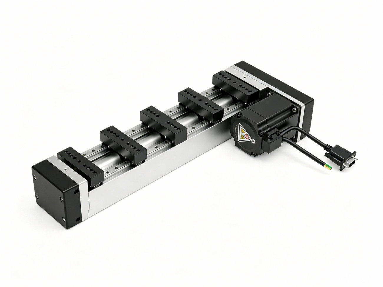
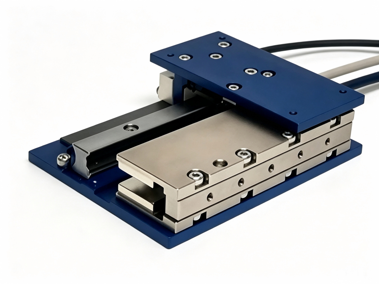
Linear servo motors provide direct linear motion and do not need the mechanical conversion components (ball screws, belts, rack-and-pinion mechanisms) that rotary motors require for linear applications. A linear motor is basically a rolled-out rotary servo motor with the forcer (which has the windings) sliding along a magnetic track. Linear motors do away with the need for mechanical transmission components, leading to zero backlash, higher acceleration (up to 10G or more) and higher top speeds (often beyond 5 m/s) than rotary-to-linear systems. They are used in applications such as inspection of semiconductor wafers, high speed pick and place, precision laser machining and other applications requiring extreme dynamic performance. The trade-offs are increased cost, the need for precise alignment during installation and more complicated thermal management.
Direct-drive torque motors (DD motors or ring motors) are large diameter, high-pole count servo motors designed to drive a load directly without a gearbox or other speed-reducing mechanism. Direct-drive systems have no mechanical transmission components between the motor and the load, resulting in zero backlash and excellent stiffness, and are ideal for rotary tables, robot joints, telescope mounts, and precision indexing applications. If you need more torque multiplication, you can pair a standard servo motor with a precision planetary or harmonic gear reducer to achieve the output torque you need while still maintaining precision.
Servo Motors in Various Industries: Common Applications
Nearly every manufacturing industry uses servo motors, with heavy concentration in robotics (articulated and collaborative), CNC machining and metalworking, semiconductor and electronics manufacturing, packaging and material handling and medical device manufacturing.
In robotics, servo motors are the actuators that drive every joint of articulated robot arms, enabling the coordinated multi-axis motion required for welding, painting, assembly and material transfer. A typical 6-axis industrial robot has 6 AC servo motors, one for each joint. Each motor has its own encoder and drive. Collaborative robots (cobots) that are designed to work next to humans use servo motors with integrated torque sensing to detect unexpected contact and come to a safe stop. Compact DC servo motors for wheels, lift mechanisms and end-effector actuators drive service robots in logistics and warehousing.
In CNC machining and metalworking, servo motors are used to drive the axes of milling machines, lathes, grinding machines, and electrical discharge machines (EDM). The accuracy of the positioning of the servo axes is directly related to the dimensional accuracy of the finished part. Servo motors with direct drive or high-rigidity coupling are used in high-end CNC machines to reduce backlash and mechanical compliance. Many modern CNC machines have a spindle motor which is itself a high-speed servo motor, which can be precisely controlled for speed for cutting, but also for rapid positioning for tool changes.
Servo motors offer the high precision necessary for semiconductor and electronics manufacturing processes such as wafer handling, die bonding, wire bonding and inspection. The semiconductor industry requires positioning accuracies in the nanometer range and motion smoothness to avoid defects induced by vibrations. This is an area where linear servomotors and direct drive stages are standard, since eliminating mechanical transmission components is crucial to achieving the required precision. Servo-driven alignment systems offer the sub-micron positioning accuracy required for fiber optic coupling and photonic chip assembly, as discussed in our review of precision motion control in optical communication manufacturing.
In high-throughput production lines for packaging and material handling, servo motors deliver the speed, flexibility, and repeatability required. In form-fill-seal machines, cartoners and case packers, electronic camming replaces mechanical linkages, allowing product changeovers to be done with software parameter changes, not hours of mechanical adjustments. The servo drives on the conveyors provide independent speed and position control of each product carrier, allowing asynchronous motion profiles that increase throughput by removing the fixed-pitch constraints of traditional chain conveyors.
In medical device manufacturing and lab automation, servo motors facilitate the exacting liquid handling, sample positioning, and assay processing needed for diagnostic equipment, drug discovery platforms, and surgical robots. The small size and quiet operation of precision servo motors, qualify them for bench top instruments and portable medical devices where space is at a premium.
Other important application areas are textile machinery, printing presses, automotive production lines, renewable energy (solar tracker positioning and wind turbine pitch control), aerospace actuation and entertainment automation (motion simulators and stage effects).
Selecting the Best Servo Motor for Your Application
To choose the right servo motor, a systematic evaluation of the load characteristics (inertia, torque, speed), the mechanical transmission (direct drive, gear reducer, ball screw, belt), the motion profile (acceleration, duty cycle), the environmental conditions, and the control architecture is critical; followed by matching these requirements to a motor that operates within its continuous and peak ratings with adequate safety margin.
The selection process starts with a complete characterization of the mechanical load. Find the load inertia. This is the rotational inertia of everything the motor has to accelerate, including the load itself, couplings, pulleys, and any intermediate transmission elements. A load-to-motor inertia ratio of less than 10:1 is generally recommended for high-performance servo systems and less than 5:1 for applications requiring the highest dynamic response. If these ratios are exceeded, instability, ringing and difficulty in tuning may result. If the inertia ratio calculated is too high a gear reducer or larger frame motor is needed.
Then, define the motor motion profile: the sequence of accelerations, constant speed sections, decelerations and dwell times the motor must perform. From this profile, calculate the RMS (root mean square) torque, which is the equivalent constant torque which would produce the same heating as the real varying torque. The RMS torque must be lower than the continuous rated torque of the motor. Also calculate the peak torque requirement – the maximum instantaneous torque required during the most demanding segment of the motion profile, usually during acceleration. The motor’s peak torque rating needs to be higher than this number, typically 20 to 30 percent.
You have to check the speed requirements against the torque-speed curve of the motor. The AC servo motor can produce full continuous torque up to the rated speed. Above the rated speed, in the constant-power region, the torque available decreases inversely with speed. Verify that the required torque at the maximum working speed is within the capacity of the motor.
The type of mechanical transmission also has an influence on the motor sizing calculation and on the precision that can be achieved. Ball screws are a common part of linear motion systems. The rotary motion of the motor is converted to the linear motion of an axis. The lead of the ball screw defines the relationship between the motor RPM and the linear speed. The gear reducers do increase the torque and decrease the reflected load inertia by the square of the reduction ratio. So a 5:1 reducer decreases the reflected inertia by a factor of 25. The direct drive configurations remove compliance and backlash but require motors with higher torque output as there is no mechanical advantage from the reduction of speed.
We cannot forget the environmental influences. Motors used in washdown environments need IP65 or IP67 sealing. High ambient temperature installations may require derating the motor’s continuous torque capability. Optical encoders are not suitable for high-vibration environments and rugged feedback devices such as resolvers are required. Cleanroom motors shall comply with particle emission and outgassing specifications.
Finally, the control architecture, communication protocol (EtherCAT, CANopen, PROFINET, pulse-and-direction), safety requirements (STO, SS1, SLS), and features such as electronic camming or registration mark alignment must be checked for the capabilities of the selected servo drive.
If you need more detailed advice, refer to the servo motor troubleshooting FAQ. It can guide you through typical selection issues and help you steer clear of specification mistakes that may cause performance problems or premature failures.
Common Problems and Maintenance of Servo Motor
Modern servo motors are designed for long service life and little maintenance, but proactive inspection of electrical connections, mechanical couplings, cooling systems and feedback devices, and periodic verification of the drive parameters, prevent the most common failure modes and increase the operational availability.
In industrial areas, the most common problems with servo motors are encoder communication errors, bearing wear, overheating, electrical noise interference and mechanical misalignment. Many of these can be prevented or detected early by means of structured maintenance procedures.
Encoder faults are often signaled by intermittent position errors, unexplained following error alarms or loss of absolute position at power up. Encoder disc is dirty (dust, oil, condensation). Feedback cables are loose or damaged. Electrical noise is coupling into encoder signals. Preventive measures include ensuring that all connectors are fully seated and free from corrosion, inspecting cables for cuts, kinks, or tight bend radii, and keeping the encoder housing sealed. For absolute encoders with battery backup, the backup battery shall be replaced at the interval recommended by the manufacturer (typically one to three years).
There are no brushes to replace, so the main mechanical wear in AC servo motors is bearing wear. Bearings are rated for 20,000 to 30,000 hours of operation at rated load. This number can be greatly reduced by radial or axial overloads, misalignment, contamination or poor lubrication. Symptoms include increased noise (grinding, clicking or squealing), increased vibration levels and increasing motor temperature. Critical production equipment is usually replaced proactively based on operating hours, rather than waiting for a failure to occur. Be careful when replacing bearings though, it is possible to demagnetize or damage the rotor magnets if the motor is not handled properly.
Many things can cause overheating. Running the motor above the continuous torque rating for extended periods. High ambient temperature. Restricted airflow around the motor. A failing cooling fan. Most servo motors have embedded temperature sensors (thermistors or RTDs) that are monitored continuously by the drive. Persistent over-temperature warnings should not be ignored. Resetting the fault and continuing operation without correcting the root cause can result in permanent damage to winding insulation and rotor magnets.
Electrical noise can manifest itself as erratic motor behavior, unexplained position jitter, or communication dropouts. Good grounding practices are important: the motor frame, drive chassis, and machine structure should all share a common ground reference through low impedance connections. To reduce inductive coupling, power cables and feedback cables should be separated by a minimum of 150 mm. Encoder signals should be carried on shielded cables with the shield terminated at both ends (drive and motor). Ferrite cores on encoder and communication cables can suppress high frequency common mode noise.
Mechanical misalignment between the motor shaft and the driven load is a common root cause of premature bearing failure, increased vibration and degraded positioning accuracy. Flexible couplings can tolerate minor misalignment but do not replace correct shaft alignment. Laser alignment tools can provide angular alignment to within 0.05 degrees and parallel offset to within 0.01 mm, which maximizes coupling and bearing life.
A good maintenance program consists of quarterly visual inspections, annual electrical testing (insulation resistance, winding resistance), trending of vibration analysis and scheduled replacement of wear items such as bearings, seals and encoder batteries based on operating hours. Keeping maintenance logs that document inspection findings, parameter changes and failure events can help you facilitate trend analysis that can predict failures before they cause unplanned downtime.
The Future of Servo Motor Technology
Servo motor technology is evolving towards higher power density, integrated intelligence with onboard diagnostics and predictive maintenance, native multi-protocol communication and closer integration with digital twin and AI-driven optimization platforms.
The trend to smaller and more powerful motors continues unabated. Higher performance rare-earth magnet materials, better winding techniques (such as segmented stator and hairpin winding) and better thermal management are all contributing to motors with more torque in smaller frames. This miniaturization is in line with the general trend in the industry for smaller machine designs and collaborative robots working in shared human workspaces.
Smart servo drives with built-in edge computing power are changing maintenance from reactive to predictive. By continuously monitoring motor current signatures, vibration spectra and temperature trends, onboard algorithms can detect early signs of bearing degradation, winding insulation breakdown or mechanical looseness and alert maintenance teams before a failure disrupts production. These diagnostics can reduce the need for periodic manual inspections and can aid in condition-based maintenance scheduling.
Communication protocols have converged. EtherCAT and PROFINET IRT have emerged as the dominant real-time Ethernet protocols for demanding multi-axis servo applications. The use of standardized protocols makes integration easier, reduces the types of spare drives and cables to be stocked, and makes it possible for components from different vendors to work together.
Digital twin technology creates a virtual twin of the servo system, which runs in parallel with the physical machine, and allows for offline simulation, commissioning and optimization. Engineers can experiment with motion profiles, adjust control parameters, and validate cycle times in a virtual environment before deploying to physical hardware. AI-based auto-tuning algorithms can learn over time the mechanical properties of a machine, and adaptively tune control gains to maintain optimal performance when components wear, or when operating conditions change.
All in all, these trends indicate servo systems that are more integrative, more reliable in operation and more intelligent in self-diagnosis, underscoring the pivotal role of servo motors in the future of industrial automation.
Frequently Asked Questions (FAQ’s)
Why does a servo motor make a buzzing or humming sound when powered up?
Servo motors tend to buzz or hum quite a bit, and some mild humming is usually not something to worry about. Several things contribute: electromagnetic vibration from the stator’s magnetic field interacting with the rotor; standstill holding current that the drive supplies to lock the rotor in place; PWM drive switching noise which is more noticeable at rest or low speeds; mechanical resonance caused by misaligned couplings, loose mounts, or binding loads; and micro-positioning corrections as the servo continuously makes tiny adjustments to maintain target alignment. If the buzzing is loud or accompanied by vibration, check mechanical coupling alignment, tighten all mounting hardware, incrementally reduce position and speed loop gains, and enable standstill current reduction if available in the drive parameters.
What is the typical lifespan of a servo motor?
The life of a servo motor is dependent on the operating conditions, load profiles and maintenance practices. The bearings are typically the limiting life component, and are rated for 20,000 – 30,000 hours of operation at rated load and proper alignment. Clean, well maintained, and conservatively loaded conditions can be expected to provide decades of reliable service from servo motors. Continuous operation in overload, frequent rapid acceleration and deceleration cycles, which generate bearing stresses, high ambient temperatures, ingress of contamination and misalignment with the driven load all reduce service life. Regular vibration monitoring and scheduled bearing replacement based on operating hours can optimize the service life of critical production motors.
Do servo motors require gear reducers?
It’s not always the case but gear reducers are used with servo motors for three main reasons. First, they increase the torque output so that a smaller, less expensive motor can drive a high-torque load. Second, they reduce the inertia of the reflected load by the square of the reduction ratio, which makes it easier to accelerate and decelerate the load accurately. Third, they provide a mechanical speed reduction that could improve positioning resolution with incremental feedback. In many applications where high torque at low speed is required (e.g., rotary indexing tables, heavy conveyor drives, robot base joints, etc.), servo motors are often used in conjunction with precision planetary or harmonic gear reducers. However, direct drive applications intentionally do not use gear reducers in order to eliminate backlash and mechanical compliance, at the expense of requiring a larger, higher torque motor.