Today, manufacturing and industrial automation need more precision, speed and reliability than traditional motors can provide. The difference between accepting and rejecting a part can be just a fraction of a millimeter, so engineers and system integrators depend on a specific motor technology to control machine movement, component positioning and response. As production lines become more complex in semiconductor fabrication, new energy manufacturing, 3C electronics assembly, precision laser processing, and smart logistics, high-performance motion control is now an operational necessity, not just a competitive advantage.
Across these industries, engineers, procurement managers, and other technical decision makers are faced again and again with the same question: What technology can provide the closed-loop precision necessary for today’s most demanding motion tasks? In most cases the answer is one piece of equipment.
A servo motor is an electromechanical device that uses closed-loop feedback for precise control of position, speed and torque. Unlike a regular motor that just spins when powered, it continuously measures its output with an integrated sensor, typically an encoder, and compares the measurement to the commanded target. If they are not the same, the servo drive rapidly corrects current, voltage or frequency to reduce the error to a minimum. The end result can be accuracies to fractions of a degree angular or sub-micron linear displacement.
What separates the servo motors from the standard AC induction motors, DC motors and even stepper motors is this feedback based architecture. All motors convert electrical energy into mechanical rotation, but the servo motor is built around the idea of error correction in real time. Anyone specifying, buying or maintaining industrial automation equipment needs to understand how that process works, what components make it possible and where servo technology delivers the best bang for the buck.
This guide looks at how servo motors are built, how they function and where they are used. It explains the materials that go into their fabrication and their part inclosed-loop systems, then discusses why they’ve become essential in robotics, CNC machining and automotive systems. By the end, you will know what a servo motor is, how it works, what it is used for and how to select the right servo solution for your specific application.
What Is a Servo Motor?
A servo motor is a rotary/linear actuator that enables precise control of angular or linear position, velocity and acceleration. It has a closed loop system with a motor, a feedback sensor and a dedicated servo drive. The key difference is not the physical build of the motor but how it’s controlled. It can keep correcting itself to stay very close to the commanded input with very little error between real output and commanded input because it receives feedback in real time.
The word “servo” is derived from the Latin word servus, meaning servant or slave. This is the origin. It matches the role of the motor. It gets commands from a controller, then reports its actual state. That attention to accuracy is what sets servo motors apart from open-loop systems that provide no verification that the requested motion actually took place.
It is rare that servo motors are used alone for industrial applications. Usually they are part of an integrated motor and drive system, which also includes a servo drive (amplifier), a feedback device such as an encoder or resolver, and a motion controller or PLC. Commands from the controller are typically sent as pulse trains, analog voltage signals, or digital protocols such as EtherCAT or Modbus. The drive provides the current the motor windings need and the encoder constantly feeds position data to the drive. This feedback loop is real time, so the system can detect errors and correct them in milliseconds.
Servo technology is only useful in the ability to control position and speed.
Position Control: A servo rotates to a specified angular position and holds it there with high accuracy and repeatability.
Speed Control: It accurately controls the speed of rotation even with change in load.
Torque Control: Accurately controls the output torque, important for winding, tensioning and press-fit assembly.
Motion control products are available in a broad power spectrum. Miniature servo motors can be under 50 watts and fit inside compact medical devices. Large industrial units can be over 15 kilowatts for heavy machinery. One advantage is the scalability, another is the inherent precision of closed loop control. All these features combined have made servo motors the standard choice where positioning cannot tolerate any error.
How Servo Motor Works?
The controller issues a command to the servo motor. This energizes the stator windings and produces the rotating magnetic field that turns the rotor. An encoder measures the actual position of the rotor and the system constantly compares this with the commanded position. Any difference between the two produces a following error, and the servo drive changes its output current until that error is close to zero.
One way to understand the process is to follow the coordinated events that happen hundreds or thousands of times per second:
The target position, speed or torque is calculated by the application program of the motion controller or PLC. It then sends accurate pulse commands that define the distance and speed of the movement.
The command is taken by the servo drive and converted into a modulated electrical current, which is then applied to the motor’s stator windings in a predetermined sequence. Pulse-width modulation (PWM) directly gives the strength and velocity of the rotating magnetic field by the amplitude and frequency of the current.
The rotating magnetic field produced by the stator acts on the permanent magnets in the rotor, causing the rotor to rotate. That is the principle of every electric motor.
At the same time an encoder mounted on the shaft is continuously monitoring the actual angular position, speed and direction of the rotor. Many industrial grade AC servo motors with 21 bit resolution (which is enough to resolve more than 2 million discrete positions per revolution) are using modern high resolution encoders, with accuracy of less than one arc minute.
The encoder feeds live data to the servo drive; The drive compares those readings with the commanded values in its own specific control loop. The drive uses PID (Proportional-Integral-Derivative) algorithms to find the required correction.
When the deviation is sensed, the drive instantly adjusts the output current to move the rotor back to the proper alignment. The cycle repeats, often at frequencies between 2 kHz and 16 kHz, and the system can correct itself thousands of times per second.
When the motor has reached the commanded position, the drive continues to provide current to hold the rotor firmly against any external forces. Torque generation while stationary is important for applications such as robotic arm joints and precision alignment stages.
Servo drives today are much more sophisticated than in the past. Many support communication protocols such as EtherCAT, Modbus and Profinet, so they can interface with complex multi-axis automation networks. Also the behaviour of the drive can be adjusted automatically by auto-tuning, vibration suppression and notch filters. That means commissioning takes less time and requires fewer specialists.
One of the main features that separates one servo system from another is the speed of this feedback loop. A drive with higher bandwidth reacts faster to disturbances and command changes and thus has less overshoot, shorter settling times and better dynamic performance. Bandwidth often limits the maximum throughput possible in high speed applications such as semiconductor die bonding and laser marking.
What Does a Servo Motor Consist Of?
There are three main subassemblies for the servo motor. These are the motor body (stator and rotor), the feedback device (encoder or resolver), and the housing assembly. The stator usually comprises laminated silicon-steel cores with windings of copper wire. The rotor is different, employing high-grade rare-earth permanent magnets such as neodymium-iron-boron (NdFeB). The precision optical or magnetic sensing elements are embedded in the glass or metal disc of the encoder. The disc and other components are housed in an aluminum-alloy or cast-iron casing that is designed to handle heat and keep out environmental contaminants.
The materials and construction techniques used in servo motors directly dictate their performance, affecting torque density, efficiency, thermal limits and service life. The following section examines each sub-system and the materials used in construction.
Stator Group
The stator creates the rotating electromagnetic field for the motor, but doesn’t move. Its core is made from stacked, bonded silicon-steel laminations, usually 0.35 mm or 0.5 mm thick. This design uses a layered core to minimize eddy current losses that would otherwise produce excessive heat and reduce efficiency.
The laminated core has carefully formed slots into which copper magnet wire is wound in specific patterns. The distribution or concentration of the winding can affect the characteristics of the torque, cogging and the speed range of the motor. For reliable operation at high current continuously, the manufacturers use high grade copper with high conductivity and the right insulation class. Usually, class F or H (155°C or 180°C respectively).
Rotor Assembly
The rotor is the spinning part and one of the most sophisticated parts of the servo motor. The most common type of modern AC servo motors is the permanent magnet synchronous motor (PMSM). Its rotor uses strong rare-earth magnets instead of conductive bars or wound coils.
Servo motors typically use neodymium-iron-boron (NdFeB) magnets, the highest energy product commercial magnetic material. Their use allows for exceptional torque density, providing more torque in a smaller, lighter package than ferrite or alnico magnets can. Some high performance machines use segmented magnet arrangements or skewed pole designs to reduce cogging torque and provide smoother low speed operation.
The rotor shaft is made of alloy steel, precision machined and supported by high grade bearings. Deep-groove ball bearings are the usual choice. Angular contact bearings are selected for applications with high axial and radial load capacity. The quality of the bearing directly affects the runout of the motor, the vibration and the life of the motor.
Feedback and Encoder System
The encoder is arguably what separates a servo motor from a regular motor because it provides the feedback signal necessary for closed loop control. There are several well-established encoder technologies:
Encoder Type
Resolution
Accuracy
Robustness
Typical Application
Incremental Optical
Max. 10,000 PPR
Moderate
Moderate
General Automation
Absolute Optical
17-25 bit (131k-33M counts/rev)
High
Moderate
Robotics, CNC
Magnetic Encoder
12-17 bit
Medium
High (dust, oil)
Severe environments
Resolver
Analog (continuous)
Moderate (R/D conversion)
Very High
Extreme temperature, shock
Inductive
15-19 bit
High
High
Machine tools
In the production of semiconductors, high precision AC servo drives are used with absolute encoders for sub-micron positioning accuracy. In case of power loss, an absolute encoder retains the position information, unlike an incremental encoder, which allows the system to restart without a homing sequence.
Thermal Management and Enclosure
The motor housing has multiple functions at the same time. It gives structural support, dissipates heat, protects the motor from environmental conditions and provides electromagnetic interference shielding. The most popular choice is aluminum alloys, which have excellent thermal conductivity, yet are lightweight and corrosion resistant. Motors used in harsh industrial environments may have a cast iron housing to increase durability.
Thermal management should be carefully considered during the design process. The stator windings in high torque servo motors generate a lot of heat. High temperatures can degrade magnet performance through demagnetization, reduce the life of the winding insulation and cause thermal expansion that affects precision. To improve convective heat transfer, cooling fins are commonly used on the outside of the housing. High rated models may need forced air cooling or liquid cooling if operated at high torque continually.
The IP (Ingress Protection) code tells you how well protected a motor is from environmental conditions. Most industrial servo motors are IP65 or IP67 rated, making them dust resistant and, depending on the rating, resistant to water jets or temporary immersion. Different protection level for different installation environment.
Other Sections
A complete servo motor assembly will also typically include several other parts besides the main motor body and encoder.
Brake: This is an electromagnetic brake that engages when power is removed to prevent the load moving under gravity in vertical axis applications.
Connectors: Industrial circular connectors for power and signal cables, often rotatable or angled to assist with cable routing.
Shaft Seal: Lip seal or V-ring at the shaft exit preventing entry of foreign matter and lubricant for the bearing in.
Thermistor or Thermal Switch: Temperature sensors built into the motor that tell the drive to cut current or sound an alarm when the motor gets too hot.
When properly sized and operated within its specifications, the engineered components work together to enable a servo motor to reliably complete millions of cycles with repeatable accuracy.
What is the use of a servo motor?
Servo motors are used in applications where precise control of position, speed, or torque is needed, and in applications where real time correction based on feedback is needed. They are used in industrial robots, CNC machine tools, automated packaging systems, semiconductor manufacturing equipment, textile machines, printing presses, medical devices and electric-vehicle subsystems. Servo motors are often the actuator of choice when you need fast, accurate motion that needs to be repeated reliably in a process.
Servo motor applications are used for many of the key industry segments:
Industrial robots: Robotic arms, whether they are articulated 6-axis, SCARA systems or collaborative robots, rely almost entirely on servo motors at their joints. Each motor has to accelerate its arm segment, quickly, to stop exactly at the target and hold there against gravity and process forces. The axes also need to be synchronized. A slight lag or overshoot at one joint can magnify the positional error of the end-effector as it passes through the kinematic chain.
CNC Milling: In CNC milling, turning, grinding and EDM machines the cutting tool is moved relative to the workpiece by servo motors using ball screws or linear motors. The positioning accuracy is usually within ±0.005 mm – ±0.01 mm and the feed rates of high-speed machining centers can be more than 30 m/min. A small positioning error can become a dimensional error in the end part.
Packaging and Converting: In food, beverage, pharmaceutical and consumer goods manufacturing, servo motors fill, cap, label, carton and palletize in high-speed packaging lines. Electronic camming and gearing allows precise synchronization of multiple servo axes without the use of mechanical line shafts and allows fast changeovers between product formats. Components are selected for the needs of high-throughput packaging environments and are supplied by industrial automation suppliers.
Electronics and Semiconductor Manufacturing: It’s probably the industry where motion accuracy is most critical. Wafer-handling robots, die bonders, wire bonders, pick-and-place machines and lithography stages all need to position components at the nanometer level. This is made possible by servo-controlled linear motor stages which enable frictionless movement with no backlash.
Conversion & Printing: Servo motors are used on flexo, gravure and digital presses to keep the color stations in precise register. If it’s even a few microns off, there will be visible defects in the print. The same systems are used on high speed rotary converting lines with servos controlling web tension and cut-off registration.
Medical Equipment: Servo motors are used in surgical robots, diagnostic imaging equipment such as CT scanner gantries and X-ray positioning systems, laboratory automation and prosthetic devices. These applications need more than precision. The motors also have to endure sterilization, have low acoustic noise and be safe in case of failure.
Renewables: Solar tracking systems use servos to follow the sun across the sky, keeping photovoltaic panels oriented toward it and helping to maximize energy capture. Wind turbines use servo actuators differently. They adjust the angle of the blades to maintain aerodynamic performance and protect the turbine in a storm.
Machinery Textile: Servo motors are used in place of conventional mechanical cams and linkages on high-speed weaving looms, knitting machines, and embroidery equipment. Thus the patterns may be changed with virtually no limitations, and the formats may be changed rapidly without mechanical reconfiguration of the equipment.
Automotive Manufacturing: Servo motors are not just for the factory floor, where they’re used in welding robots and automated assembly cells. They also are installed within vehicles, which often causes people seeing the technology for the first time to ask a question.
What is a car servo motor?
A car servo motor is a compact and precise electric motor that drives mechanical components based on instructions from the electronic control unit (ECU). Rather than appearing as the large industrial servos used on factory floors the automotive versions are built into various vehicle systems. They control functions such as throttle actuation, HVAC blend-door positioning, headlight leveling, power-seat adjustment, and the calibration of advanced driver-assistance system (ADAS) sensors.
Today, servo motors are a standard part of automotive design, as the industry has moved from mechanical and hydraulic controls to electronic “drive-by-wire” architectures. Older cars used physical cables, linkages, and vacuum actuators. Networked systems in today’s vehicles combine sensors, ECUs and compact servo motors and provide faster responses, less weight and greater design flexibility.
Electronic Throttle Control (ETC): The air intake to the engine was regulated by a simple cable from the accelerator pedal to the throttle butterfly valve. Today, an electronic throttle body uses a DC servo motor instead. When you press on the accelerator, a pedal position sensor sends a signal to the engine control unit. The ECU then sends a command to the throttle servo motor to open the valve to some angle. The motor has a built-in position sensor which verifies the requested angle has been reached so the ECU can adjust fuel injection and ignition timing accordingly. The system also enables cruise control, traction control and stability control to adjust the power of the engine without any driver input.
HVAC Controller: A modern vehicle’s heating, ventilation and air conditioning system may contain five or more small servo motors, which are often called actuator motors here. These motors are located inside the HVAC housing and move the blend, mode and recirculation doors that direct airflow through the system. When you choose a temperature or airflow setting with the driver or automatic climate control, the related servo rotates its door to the precise position that will give the cabin conditions you want. They work quietly and don’t constantly use power when they hold their position, which makes the vehicle save energy.
Headlight Adjustment and Adaptive Headlights: Many jurisdictions also require automatic leveling systems on vehicles with HID or LED headlights. The systems change the beam when the vehicle pitches with changing loads or acceleration to keep glare out of the eyes of oncoming drivers. There is a servo motor on each headlight assembly that changes vertical aim in response to signals from suspension height sensors. More sophisticated adaptive front lighting has additional servo motors to rotate the beam in conjunction with the steering, enhancing visibility around bends at night.
Power Seat Adjust: Power seats with 8-way, 12-way or even more adjustment options are commonly found in luxury and mid-range vehicles. Each axis – fore-aft position, height, tilt, lumbar support, bolster width – is moved by small DC servo motors. The system can save the settings as well. A seat control module that stores preferred positions and recalls them at the push of a button, often via individual driver profiles.
Placement of ADAS Sensors: Advanced driver assistance systems depend on the accurate alignment of radar, lidar and camera sensors. In some vehicles, servo motors adjust the orientation of the sensors, as the vehicle pitches or rolls under acceleration, braking, or cornering, in order to keep the field of view properly aligned to detect obstacles and track lanes.
There are several differences between automotive and industrial servo motors. They have to work over an extreme temperature range, typically -40°C to +125°C, and at the same time survive vibration and shock. Housings have to be sealed against moisture and dust and the motors have to comply with strict electromagnetic compatibility (EMC) standards. Another big limitation is cost. To maintain low prices, manufacturers might opt for less expensive magnetic materials, simpler manufacturing processes (often potentiometer-based encoders in HVAC actuators), and highly automated production.
Servo Motors Types
To choose the right technology for an application, you must know the different types of servo motors. All of them employ closed-loop control, but they can differ greatly in their physical design, power characteristics, and the applications for which they are best suited.
AC Servo Motor
AC servo motors are used widely in industrial automation. Most are three-phase permanent magnet synchronous motors (PMSM) with sinusoidal back-EMF waveforms and sinusoidal current from the servo drive. This results in very low ripple of the torque, which is important for high-precision applications.
Key Features:
Power output from 50 W up to 15 kW and more.
Most models run from 0 to 6,000 RPM, with some models reaching 10,000 RPM.
The high torque to inertia ratio provides rapid acceleration with extremely smooth low speed operation.
These motors are brushless, so they last a long time and require very little maintenance.
They are used in robotics, CNC machines, packaging equipment and other demanding industrial motion applications. The bandwidth and accuracy necessary for semiconductor manufacturing, provided by high-end AC servo technology.
DC Servo Motors
DC servo motors are built around brushed DC motors, where the stator consists of permanent magnets and the rotor has windings. Mechanical commutation is performed by brushes and a commutator, so the drive electronics can be simpler and cheaper than for AC or brushless DC motors.
Key features:
The output power is generally below 2 kW.
Simple PWM DC drives are employed.
They have high starting torque.
Torque varies linearly with speed.
The brushes should be changed from time to time.
DC servo motors are still used in vintage CNC equipment, lab equipment, and in budget applications where the brushes can be replaced as a maintenance item. But in new industrial designs they have been mostly replaced by brushless AC servo motors.
Brushless DC (BLDC) Servo Motors
BLDC motors are technically in the permanent magnet synchronous motor family. They are, however, often considered a separate class because of their trapezoidal back-EMF waveform and use of a simpler six-step commutation method. In this sense they are a compromise between brushed DC motors and true AC servo motors.
Main features:
Power output is from 5 W to several kW
More efficient than brushed DC motors.
Longer service life, as the brushes do not wear out
A drive system simpler than that of a true sinusoidal AC servo
At low speeds there is a small torque ripple.
BLDC servo motors are widely used in medical pumps, drone propulsion systems, computer cooling fans, and automotive auxiliary systems.
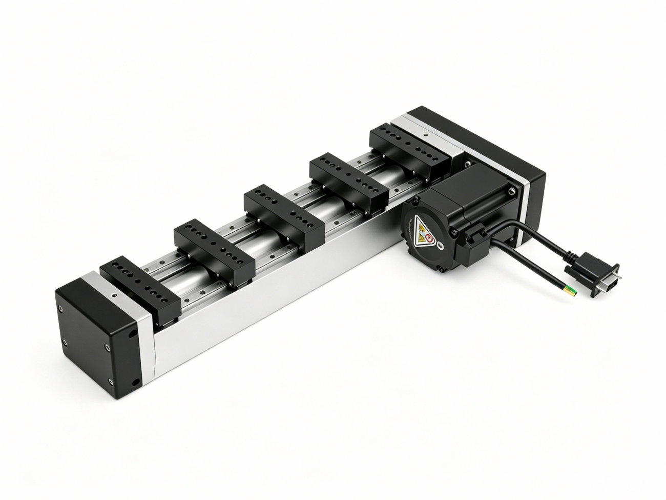
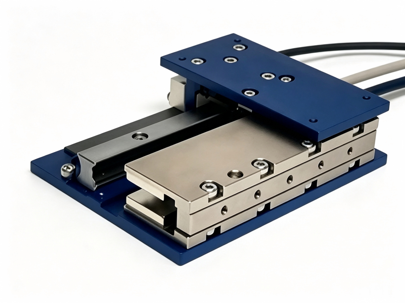
Linear servomotor
Linear servo motors provide direct straight line motion, without the use of a screw, belt, or other means of converting rotary motion into linear motion. They are similar to rotary servo motors “unrolled” into a flat configuration where the stator, or forcer, moves over a linear magnet track.
Key features:
Direct drive, no back lash or backlash
Acceleration up to 10 G and above
Velocity > 5 m/s
Linear encoder feedback for sub-micron positioning
More expensive than screw driven options
Linear servo motors are the choice for semiconductor wafer stages, precision laser cutting, high-speed pick-and-place, and other applications where ball-screw limitations such as whip, wear, and thermal expansion are no longer acceptable.
Integrated servomotors
An integrated servo motor is a compact combination of the motor, encoder, drive electronics and motion controller. So no separate drive cabinets and no motor cables are required and the wiring is easier.
Key features:
Reduced wiring, Smaller panels
Simpler installation
Control distribution across the system
Generally restricted to low power levels (less than 1 kW)
Integrated servo motors are playing a greater role in modular machine designs, as the distribution of intelligence across the system provides more flexibility and scale.
Table of Comparison
Type
Power Range
Control Complexity
Maintenance
Precision
Price
AC Servo (PMSM)
50 W – 15+ kW
High
Low
High
High
DC Servo (Brushed)
< 2 kW
Low
Medium (brushes)
Moderate
Low-Medium
BLDC Servo
5 W – a few kW
Medium
Low
Moderate-High
Medium
Linear Servo
Variable
Very High
Very Low
Ultra High
High-High
Integrated Servo
< 1 kW
Standalone
Low
High
Medium
Servo Motor vs Stepper Motor: Which technology should you choose
The servo motor or the stepper motor is a popular choice when designing for motion control. Both can place a load, but they operate in very different ways. A wrong choice can mean poor performance, unnecessary cost, or continued reliability problems.
Major Difference
Criterion
Servo Motor
Stepper Motor
Control Method
Closed loop with encoder feedback
Generally open loop
Position Verification
Real time and continuous
None unless encoder is added
Torque @ Speed
High torque across speed range
Torque drops quickly with speed increase
Overload Capability
300% of rated torque for short durations
None; motor stalls when overloaded
Efficiency
High as it draws only the required current
Lower as it draws full current even while stationary
Noise & Vibration
Smooth and quiet operation
Audible noise and resonance issues
Cost
Higher
Lower
Complexity
More complex setup and tuning
Simple pulse and direction control
Accuracy
Sub-arc-minute with high resolution encoder
±0.9° or ±1.8° per full step without microstepping
When to Use a Servo Motor
Servo motors are a great choice when an application requires operation above 1,000 RPM without sacrificing torque, or when load changes are unpredictable and must be compensated for while the motor is holding position.
Position verification needed for safety and quality assurance.
Also the smooth motion with low vibration contributes to a constant quality of the process.
The duty cycle is one of frequent and rapid acceleration and deceleration.
Energy efficiency has a major impact on the lifetime cost of the equipment.
When a Stepper Motor is Good Enough
They remain a practical choice for applications that do not demand high performance, primarily due to their simplicity and low cost of installation. They are good for predictable loads and moderate speeds typically below 1,000 RPM especially if an occasional missed step is acceptable or already accounted for in the design margin. Thus they are still in successful use in many cost-sensitive positioning systems, such as 3D printers, camera gimbals and small laboratory instruments.
The Emerging Hybrid: Closed-Loop Stepper Systems
One such development is the closed-loop stepper system, consisting of a stepper motor, an encoder, and a drive that feedbacks and adjusts the current. It can not equal the dynamic performance of a true servo, but it solves the main weakness of stepper motors: dropping steps. The system is more expensive than an open loop stepper but less than a full servo setup.
How to Choose the Right Servo Motor
The selection of a servo motor for an application is not just a matter of comparing power ratings. To get reliable performance over time, think about the mechanical load, motion profile, operating environment and control architecture as part of the same system.
Step 1: Creating the Motion Profile
Before doing any calculations, document precisely how the motor is intended to move the load:
Travel distance: Angular (degrees or revolutions) or linear (mm) with any gear reduction
Move time: How fast should each move be performed?
Dwell time: How much time elapses between moves?
Duty cycle: Percent of the time the motor is moving vs holding position?
Accuracy required: What is the maximum allowable positioning error?
Settling time: How fast should the load settle at its target position?
Step 2: Find the inertia and torque of the load
The main calculation when sizing a servo is the inertia of the load reflected back to the motor shaft. For most applications the ratio of the load inertia to the motor inertia should not exceed 10:1. Instead, a limit of 5:1 is recommended for systems requiring high dynamic performance. If it goes above these levels you can get instability, resonance and tuning problems.
The torque required in three different conditions has to be determined:
Continuous torque is the rms torque over the whole motion cycle and controls how hot the motor gets.
Peak torque is the highest torque output under acceleration, and must be kept under the max capacity of the motor.
Holding torque is the torque required to hold a position against gravity or external forces.
Step 3: Check speed requirements
Check that the motor’s rated and maximum speeds match the velocity profile of the application. As speed increases torque decreases, verify that the motor can still provide sufficient torque at the highest velocity required.
Step 4: Match Inertia Ratio
Calculate the ratio and verify that it falls within acceptable limits for the application. If the value is too high, a gear reducer might be needed. A planetary gear reducer, hollow rotary table or other precision gearbox can improve the match of the inertias and also multiply torque.
Step 5: Selection of Feedback and Control Architecture
Choose the encoder type (incremental or absolute) and the required resolution. A communication protocol like pulse train, analog, EtherCAT or Profinet. The choice must be compatible with the motion controller and the application’s needs for multi-axis coordination, diagnostics and data collection.
Step 6: Check for environmental compatibility
Make sure the motor is suitable for the installation environment in terms of IP rating, temperature range, vibration resistance and corrosion resistance. Motors for washdown areas, cleanrooms and explosive atmospheres need to be specially engineered.
Step 7: Look at Lifecycle Factors
As well as the initial price, think about what the motor will cost over its lifetime. Energy consumption, bearing life, maintenance requirements and the availability of spare parts and technical support are all factors. A servo motor that costs a little more to buy may be less expensive over a 10-year period of operation if it is more efficient and lasts longer.
Recap
The servo motor is at the heart of so much of today’s industrial automation. The closed-loop operation integrates a precision motor, a high-resolution feedback sensor and intelligent drive electronics. This results in much more precise motion control than can be obtained with open loop systems. The difference is important in applications from semiconductor lithography, where positioning may have to be accurate to the sub-micron level, to robotic assembly lines that require high-speed coordination. In these applications, servo motors deliver the accuracy, responsiveness and reliability that competitive manufacturing requires.
Understanding what a servo motor is, how it works, what it consists of and where it delivers value helps engineers and decision makers make smart choices when it comes to investing in motion control. That knowledge is useful when designing a machine, upgrading an existing production line or simply learning how the technology behind modern industry works.
The selection of a servo system involves consideration of the motor, drive and supporting mechanical parts as a complete unit with sound engineering analysis and the help of knowledgeable experts. HCY Automation offers integrated motion-control and automation solutions including servo motors, drives, linear modules, gear reducers and related components. Manufacturers can use this range of equipment to build smarter, faster and more reliable production systems.
FAQs
1. What makes a servo motor different than a normal motor?
The “standard” motor (induction motor, simple DC motor, etc.) spins when power is applied, but doesn’t have any feedback or control over the actual speed or position. A servo motor does. It has an encoder and closed loop control so it constantly tracks its output and makes real time corrections for errors. This allows it to hold to an exact angular position, maintain a constant speed as the load changes, and report its status to a controller. Things that conventional motors do not do at all.
2. Can a servo motor run continuously, or is it only for positioning?
Servo motors are made to run continuously so they are a good choice when an application needs accurate speed control for long periods of time. They are used in conveyor systems, winding machines and spindle drives to maintain the rotation speed for long periods. The drive is also able to keep its target speed even if the mechanical load changes. The feedback mechanism provides precise positioning.
3. How many years do servo motors last?
Servo motors can have very different lifespans depending on how they are operated. Industrial models routinely achieve 20,000 to 30,000 hours or more with proper maintenance. The limiting factor is often the bearings, with L10 life ratings in excess of 20,000 hours at rated load. Brushless AC servo motors do away with brush wear, and today’s servo drive electronics are designed for extended industrial use provided they are operated within the specified temperature and humidity ranges. Proper sizing and alignment do, too. Protection from the surrounding environment does, as well.
HCY Automation delivers integrated solutions across motion control, linear motion, robotics, machine vision, pneumatic systems, and precision gearboxes to help global manufacturers build smarter, faster, and more reliable production lines. Our engineering team helps you select and integrate the right motion control, robotics, and automation components for your specific application.