Learn how to size a servo planetary gearbox with this step-by-step engineer’s guide. Master torque, inertia, gear ratio, and backlash calculations to avoid costly sizing mistakes in 2026. Complete Engineer’s Guide
Why Gearbox Sizing Is the Make-or-Break Decision
Most servo motor sizing failures in the field trace back to one root cause: the gearbox was never properly sized.
An undersized planetary gearbox overheats, wears prematurely, and destroys positioning accuracy. An oversized one inflates cost, degrades dynamic response, and adds unnecessary inertia. Get the sizing right, and your motion system runs cool, holds position, and accelerates aggressively for years. Get it wrong, and the symptoms show up on the factory floor — where they cost the most.
The global servo planetary gearbox market reached USD 6.55 billion in 2026 and is projected to grow at 8.14% CAGR to USD 10.69 billion by 2032. The precision planetary gearbox segment alone was valued at USD 2.92 billion in 2026 and is accelerating toward USD 3.96 billion by 2030 at 7.9% CAGR.
With that growth comes complexity. Engineers today face more gearbox options, more servo motor brands, and more application-specific requirements than ever before. This guide is the definitive resource for sizing a servo planetary gearbox correctly — the first time.
The 6-Step Servo Planetary Gearbox Sizing Workflow
If you follow only one framework from this article, make it this six-step sequence. Each step produces a specific output that feeds the next, and each maps to a section below.
Step 1: Define Application Requirements Before Touching a Catalog
Before comparing gearbox specifications, engineers must quantify the complete load and motion characteristics of the servo axis. All sizing calculations are based on real working conditions rather than isolated datasheet figures.
1.1 Classify Your Load Type
Load Type
Characteristics
Examples
Constant steady load
Stable continuous torque output
Conveyors, pumps, fans
Variable cyclic load
Frequent start-stop, forward-reverse
Packaging indexers, tool changers
Shock impact load
Instantaneous impact forces
Stamping, sorting, pressing
1.2 Lock Down Six Constraints
Constraint
Why It Matters
What to Specify
Mounting frame & envelope
Flange size and body length are fixed by the machine
Flange dimension, max body length, shaft diameter
Available voltage class
Drive DC bus limits torque at speed
200V / 400V class, single- or three-phase
Ambient environment
Heat and ingress derate the motor
Ambient temperature, IP rating, washdown exposure
Feedback resolution
Positioning accuracy depends on encoder type
Required accuracy; incremental vs. absolute
Holding brake requirement
Gravity-loaded axes need a brake regardless of torque
Yes/no; static holding load
Budget ceiling
Filters power class, encoder grade, and brand tier
Per-axis target cost
Critical warning: Most servo torque ratings assume a 40°C ambient. Inside a sealed panel or near a heat source, usable continuous torque shrinks. Always apply a thermal derating factor if your environment exceeds 40°C.
Step 2: Calculate Load, Torque, and Inertia
This is the mathematical foundation of gearbox sizing. Get these three numbers right, and everything that follows is selection. Get them wrong, and no amount of catalog browsing will save the design.
2.1 Calculate Load Inertia
Inertia is the resistance of a body to angular acceleration. Every rotating and translating component in the drivetrain contributes to it.
The RMS torque is what determines thermal stress on the motor and gearbox. A motor that handles peak torque may still overheat if RMS torque exceeds its continuous rating.
2.3 Apply the Service Factor
Industrial applications rarely operate under ideal conditions. Shock loads, frequent starts, and rapid acceleration create additional stress.
Application Type
Service Factor
Smooth, continuous operation
1.0 – 1.2
Moderate shock, cyclic loading
1.3 – 1.5
Heavy shock, frequent reversing
1.6 – 2.0
Extreme duty, impact loads
2.0+
T_design = T_RMS × Service Factor
Step 3: Decide the Gearbox Ratio — The Most Powerful Lever in Sizing
A gearbox is the most powerful and most underused lever in servo sizing. Engineers tend to reach for a bigger motor when a reducer would solve the problem better and cheaper.
3.1 What a Gear Ratio Does
A gearbox with ratio N provides three simultaneous benefits:
The inertia reduction is the most significant effect. A 10:1 gearbox can reduce the reflected load inertia seen by the motor by approximately 100× in an ideal case. n
3.2 How to Calculate the Required Gear Ratio
Gear Ratio = Motor Speed / Required Output Speed
Example:
Motor rated speed: 3,000 rpm
Required output speed: 150 rpm
Gear Ratio = 3,000 / 150 = 20:1
3.3 The Inertia Ratio Rule
After calculating load inertia and selecting a candidate motor, the next critical validation is the inertia ratio. This ratio compares the total reflected load inertia to the motor’s rotor inertia and directly affects system stability, responsiveness, and tuning difficulty.
Inertia Ratio = J_load_reflected / J_motor
Inertia Ratio
Performance
Suitable Applications
1:1 to 3:1
Excellent controllability
Semiconductor equipment, precision robotics
3:1 to 5:1
Acceptable for most industrial apps
CNC, packaging, general automation
5:1 to 10:1
Sluggish or oscillatory unless carefully tuned
Material handling, conveyors
> 10:1
Generally unacceptable
Requires gearbox or larger motor
Practical example: Suppose your load reflects to an inertia ratio of 30:1 straight-coupled — far above the range most drives can tune well. A 3:1 gearbox drops that reflected inertia by 9×, bringing the ratio to roughly 3.3:1, comfortably inside the range servo drives handle cleanly. No larger motor required.
3.4 Common Gear Ratios for Servo Applications
Ratio Range
Best For
Typical Applications
3:1 to 10:1
High-speed positioning, light loads
Pick-and-place, indexing, fast conveyors
10:1 to 30:1
General automation, medium loads
CNC axes, medium robots, packaging
30:1 to 100:1
Heavy loads, slow-speed high torque
Rotary tables, lifting, wind turbine pitch
Step 4: Select the Motor and Gearbox Size
With your required output torque, gear ratio, and inertia ratio in hand, you can now select a candidate motor-gearbox pair.
4.1 Verify Motor Torque at the Gearbox Input
Motor Torque = Output Torque / (Gear Ratio × Efficiency)
Example:
Required output torque: 75 N·m (after service factor)
Gear ratio: 20:1
Gearbox efficiency: 95% (0.95)
Motor Torque = 75 / (20 × 0.95) = 3.95 N·m
The servo motor must provide at least 3.95 N·m continuous torque at the speed it will actually run (not just at rated speed).
4.2 Verify Speed Compatibility
Motor Operating Speed = Output Speed × Gear Ratio
Ensure the motor’s operating speed falls within its efficient speed band — typically 50–100% of rated speed. Running a servo motor at 10% of rated speed is inefficient and causes overheating.
4.3 Seven Core Gearbox Selection Criteria
Criterion
What to Check
Why It Matters
1. Torque rating
Continuous & peak torque vs. application requirements
Brings motor into efficient speed band while meeting output speed
Wrong ratio = motor overload or sluggish response
3. Backlash
≤3 arcmin for precision; ≤1 arcmin for ultra-precision
Backlash = positioning dead zone in servo loops
4. Efficiency
94–98% for planetary gearboxes
Efficiency = heat, energy cost, and motor sizing
5. Torsional stiffness
Nm/arcmin rating
Stiffness = how much the gearbox twists under load
6. Radial/axial load capacity
Bearing ratings vs. application loads
Exceeding bearing limits = early failure
7. Thermal capacity
Continuous duty rating at ambient temperature
Thermal overload = lubrication breakdown and seizure
Step 5: Size the Drive, Power Supply, and Brake
A servo motor never works alone. It runs behind a gearbox, is driven by an amplifier with its own current limit, is fed by a power supply with its own voltage ceiling, and — on a vertical axis — depends on a brake to hold the load when power drops.
5.1 Drive Sizing
Current limit must exceed the motor’s peak current demand during acceleration
Bandwidth must support the control loop update rate required by the application
Regeneration capability must handle braking energy; high-inertia or vertical axes need a regen resistor
5.2 Power Supply Sizing
Voltage determines how much torque the motor can produce at high speed (back-EMF reduces available torque as speed increases)
Power must cover continuous operation plus peak demands
5.3 Holding Brake
Vertical axes always need a brake regardless of torque sizing
Static holding torque must exceed the gravity load at zero power
Dynamic braking capacity must handle emergency stops without overheating
Step 6: Verify Against the Datasheet
Once you have a candidate, verify it against the supplier datasheet before purchase. This is where procurement earns its keep — catalog numbers are not always directly comparable across brands.
The Pre-Purchase Checklist
Check
What to Verify
Common Pitfall
Torque at actual speed
Continuous torque holds at your operating speed, not just rated speed
Assuming “1.27 N·m” applies at all speeds
Peak torque duration
The motor and drive can sustain peak torque for your acceleration phase
Peak torque figure is useless if duration is too short
Terminology
“Standstill torque” vs. “continuous stall torque” definitions vary by brand
Assuming equivalence across manufacturers
Derating conditions
Torque curves are typically at 40°C ambient; hotter environments need margin
No thermal margin = field failures
Inertia ratio
Confirmed after gearbox reduction, within recommended range
Forgetting to recalculate after adding gearbox
Sizing by Mechanism Type: Where Each System Bites
The sizing method is universal, but the traps are mechanism-specific. Here is where each mechanism tends to bite.
The trap: The screw itself often dominates the reflected inertia — a long, large-diameter screw can outweigh the payload it carries. Before assuming the motor must grow, check whether a smaller screw lead or diameter solves the inertia problem.
Gravity matters most here: On a vertical Z-axis, the continuous torque to hold and lift against gravity can exceed the acceleration torque, and it demands a brake for power-off holding.
Belt-and-Pulley Systems
The trap: Compliance. The belt stretches, so the effective inertia ratio the drive must control is higher than the rigid calculation suggests. Keep the inertia ratio conservative here, and do not tune the loop as aggressively as you would on a rigid screw.
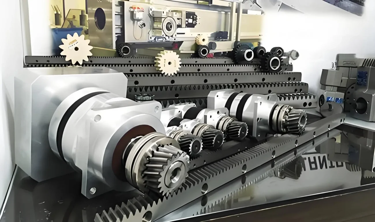
Rack and Pinion
The trap: The pinion radius sets both the reflected inertia and the force-to-torque conversion. A smaller pinion raises output force but also raises the motor speed required for a given linear speed — another speed-versus-torque trade to resolve with the gearbox ratio.
Rotary / Direct-Drive Stages
The trap: Indexing tables and direct-drive rotary stages carry the load inertia straight onto the motor with no reduction to shrink it. This is the one case where the inertia ratio is hardest to satisfy, and where a large-frame or purpose-built direct-drive motor is often unavoidable. If the ratio is impossible to meet direct-coupled, a reducer is the fix — accept the backlash trade or specify a low-backlash unit.
The 5 Most Common Gearbox Sizing Mistakes
Most servo motor sizing mistakes surface as the same handful of field symptoms. Read them as a diagnostic table — symptom first, then the sizing root cause.
Symptom in the Field
Likely Sizing Root Cause
How to Catch It Early
Overshoot, oscillation, hard to tune
Inertia ratio too high — gearbox reduction skipped or forgotten in reflected-inertia calc
Recompute reflected inertia including every drivetrain component; add or increase gearbox ratio
Overcurrent / overtemp faults after minutes
Sized against peak torque instead of RMS (continuous) torque
Verify RMS torque sits below continuous rating with margin, not just that peak fits
One axis runs fine, an identical-size axis faults
A single motor size reused across axes with different loads or duty cycles
Size each axis on its own motion profile; never copy a selection across axes by assumption
Drive trips on overvoltage during deceleration
Regeneration ignored — no regen resistor sized for braking energy
Estimate braking energy per cycle for high-inertia or vertical axes; size the regen path
Torque “disappears” at production speed
Motion profile finalized after the motor was chosen, so real speed exceeds where torque was verified
Lock the motion profile before selection; verify torque at the true operating speed
Complete Sizing Example: Packaging Machine Axis
Let’s walk through a real-world example from start to finish.
Peak current ≥ motor peak; regen resistor sized for braking energy
Power Supply
400V three-phase, capacity for continuous + peak demand
Frequently Asked Questions (FAQ)
What is the first step in sizing a servo planetary gearbox?
Define the motion profile — speed, distance, acceleration time, and dwell — since these values feed directly into every subsequent torque and inertia computation.
How do I calculate load inertia for a linear axis driven by a ball screw?
Reflect the translating mass to the motor shaft using J = m × (pitch / 2π)², then add coupling, gearbox, and rotor inertias to get the total.
How does gear reduction affect servo motor sizing?
A gearbox with ratio N divides the load inertia seen at the motor shaft by N², dramatically improving the inertia ratio and enabling a smaller motor selection. It also multiplies torque by N (minus efficiency losses).
What inertia ratio range keeps a servo system stable?
A ratio of 1:1 to 3:1 (load-to-motor) is ideal for high-performance applications. Ratios above 10:1 typically cause oscillation and poor settling regardless of tuning efforts.
Not always. A gearbox is worth considering whenever the reflected inertia ratio is too high or the load needs high torque at low speed. Direct-drive is simpler when the load is light and fast.
How much oversizing is too much for a servo motor?
An oversized motor is larger, costlier, and adds rotor inertia that degrades dynamic response. Aim for adequate margin on continuous and peak torque while keeping the inertia ratio in range.
Can I reuse the same servo motor size across multiple axes?
Only if the axes share the same load, motion profile, and duty cycle. Identical mechanical frames often have different inertia, gravity loads, or cycle times, so a size that fits one axis can be undersized on another. Size each axis independently.
What is reflected inertia in servo motor applications?
Reflected inertia is the load inertia as seen by the servo motor through the gearbox. A higher gear ratio reduces reflected inertia, helping the motor accelerate and decelerate more efficiently.
What happens if a gearbox is undersized?
An undersized gearbox leads to excessive heat generation, gear wear, reduced service life, poor machine performance, unexpected failures, and increased maintenance costs.
What efficiency can be expected from a planetary gearbox?
Most precision planetary gearboxes offer efficiency between 94% and 98%, making them one of the most efficient gearbox types available for servo motor applications.
Sizing Is a Selection Problem, Not Just a Calculation
Servo planetary gearbox sizing is not about finding the biggest torque number in a catalog. It is about defining a motion profile, calculating load and inertia, choosing a ratio that brings the motor into its efficient zone, matching the drive and power supply so the motor can actually deliver its rated torque, sizing a brake for gravity-loaded axes, and verifying every candidate against the datasheet before you buy.
Follow the six-step workflow in order, and most commissioning failures never happen — the axis fits, holds, accelerates, and runs cool at production speed. Get the sequence wrong, and the symptoms show up later, on the floor, where they cost the most.
The gearbox is the most powerful lever in servo sizing. Use it wisely.
HCY Automation delivers integrated solutions across motion control, linear motion, robotics, machine vision, pneumatic systems, and precision gearboxes to help global manufacturers build smarter, faster, and more reliable production lines. Our engineering team helps you select and integrate the right motion control, robotics, and automation components for your specific application.