Linear Motor Working Principle Explained: How It Works, Types & Applications
A linear motor produces straight-line motion directly, without converting rotary motion into linear motion through a ball screw, belt, or gearbox. This direct-drive design makes linear motors a strong choice for automation applications that require high speed, precise positioning, smooth motion, and frequent acceleration and deceleration.
But how does a linear motor actually work? What are the differences between iron-core and ironless designs? And when should you choose a linear motor instead of a conventional ball screw-driven linear module?
In this guide, HCY Automation explains the linear motor working principle, its main components, common types, advantages, and practical applications in industrial automation.
1. What Is a Linear Motor?
A linear motor is an electric motor designed to generate linear thrust rather than rotational torque. Its operating principle is similar to that of a conventional rotary motor, but its magnetic structure is arranged to produce straight-line movement.
In a rotary motor, electromagnetic force creates rotation. In a linear motor, electromagnetic force generates thrust along a straight path, allowing a moving part to travel directly along a linear axis.
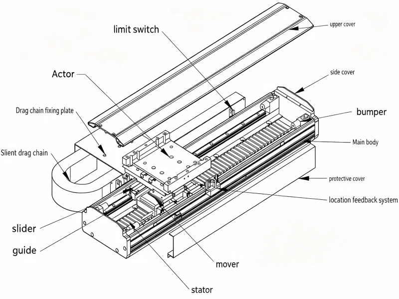
A typical linear motor system may include:
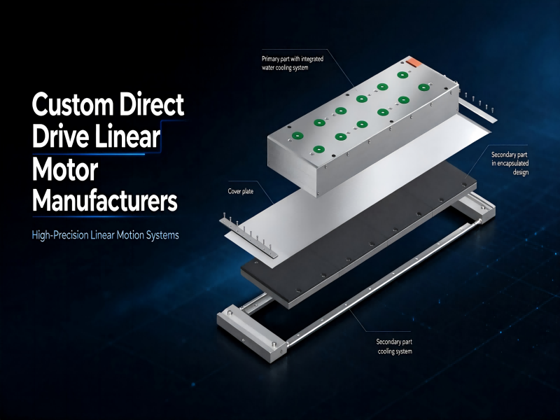
A primary section containing windings or coils
A secondary section containing permanent magnets or a conductive reaction plate, depending on the motor design
A linear guide system to support and constrain movement
A position feedback device, such as a linear encoder, when closed-loop positioning is required
A servo drive and motion controller to regulate movement
The exact configuration depends on the motor type and application. Some systems move the coil assembly while others move the magnetic or secondary section.
Unlike a conventional electric actuator, a linear motor does not need a mechanical transmission to convert rotary motion into linear motion. This reduces the number of transmission components between the motor and the load.
2. Linear Motor Working Principle: How Does It Work?
The linear motor working principle is based on the interaction between magnetic fields and electric current. This interaction generates electromagnetic force, which produces linear thrust.
The operating process can be understood in three steps.
Step 1: The Servo Drive Supplies Controlled Current
The servo drive supplies controlled electrical current to the motor windings. By regulating the current in different phases, the drive establishes a changing magnetic field along the motor’s active length.
The current and commutation timing determine the direction and magnitude of the electromagnetic force.
Step 2: Magnetic Fields Generate Linear Thrust
In a permanent-magnet linear motor, the magnetic field produced by the energized windings interacts with the field of the permanent magnets.
This interaction generates thrust along the motor’s travel direction. As the magnetic field is electronically commutated, the thrust continues to move the motor’s moving section along the linear axis.
In a linear induction motor, the traveling magnetic field induces current in a conductive secondary section. The interaction between the induced current and the magnetic field produces the force that drives the motor forward.
Although the electromagnetic details differ, both designs use electromagnetic force to create linear motion.
Step 3: Feedback Enables Precise Positioning
For applications requiring accurate positioning, a linear encoder or another suitable feedback device measures the position of the moving axis.
The controller compares the actual position with the commanded position and adjusts the motor current through the servo drive. This closed-loop control helps the system maintain the desired position and follow the motion profile.
The final positioning performance depends on more than the motor itself. Encoder resolution, control-loop tuning, mechanical rigidity, thermal stability, mounting accuracy, and the load all influence the result.
In simple terms: a linear motor converts electrical energy into linear thrust through electromagnetic interaction. With an appropriate drive, feedback system, and mechanical structure, it can deliver controlled, high-speed linear motion without a rotary-to-linear transmission mechanism.
3. Main Components of a Linear Motor System
Understanding the main components helps engineers evaluate whether a linear motor is suitable for a particular automation project.
3.1 Primary and Secondary Sections
The primary and secondary sections form the electromagnetic part of the motor.
Depending on the design, the primary may contain the windings while the secondary contains permanent magnets or a conductive reaction plate. In some motor configurations, the arrangement is different.
The relative movement between these sections produces the required linear thrust.
3.2 Linear Guide
The linear guide supports the moving assembly and constrains its travel to the required path. It also helps the system withstand external loads and moments.
Guide selection should consider payload, acceleration, mounting orientation, rigidity, travel length, and expected service life.
A linear motor generates thrust, but it does not automatically provide the mechanical support required to carry a load. The guide and mounting structure must be designed for the actual application.
3.3 Linear Encoder and Position Feedback
A linear encoder measures the position of the moving axis and provides feedback to the controller.
For precision positioning applications, the encoder and control system are critical to achieving the required repeatability and dynamic response. Encoder selection should account for resolution, accuracy, installation conditions, operating environment, and the control system’s capabilities.
Not every linear motor installation uses the same feedback arrangement. The required configuration depends on the motor, drive, and application.
3.4 Servo Drive and Motion Controller
The servo drive controls motor current and commutation, while the motion controller generates the motion commands and coordinates movement with other axes or machine operations.
For multi-axis automation equipment, communication compatibility, synchronization, acceleration profiles, safety functions, and commissioning requirements should be evaluated as part of the complete motion-control solution.
4. Types of Linear Motors
Linear motors can be classified according to their electromagnetic operating principle or their structural design. These are different classification methods, so it is important not to treat them as one interchangeable list.
4.1 Permanent-Magnet Synchronous Linear Motors
Permanent-magnet synchronous linear motors use permanent magnets and energized windings to generate thrust. The drive synchronizes the current with the motor’s magnetic position to control movement.
Common advantages include high thrust density, responsive motion control, and suitability for high-speed, high-precision positioning.
Typical applications include semiconductor equipment, precision inspection systems, electronic assembly, and automated manufacturing equipment.
Actual performance depends on the motor design, cooling method, drive, feedback device, and mechanical system.
4.2 Linear Induction Motors
Linear induction motors generate thrust through electromagnetic induction. A traveling magnetic field induces current in a conductive secondary section, and the interaction produces linear force.
They are used in applications such as certain transportation systems, industrial conveying equipment, and other applications where their operating characteristics are suitable.
Compared with permanent-magnet designs, their efficiency, force characteristics, thermal behavior, and control requirements may differ. Selection should be based on the required duty cycle and application conditions.
4.3 Iron-Core Linear Motors
Iron-core linear motors use a ferromagnetic core in the coil assembly. The core helps concentrate magnetic flux and can provide high thrust for a given motor size.
Potential advantages include:
High thrust density
Strong acceleration capability when properly sized
Suitability for demanding industrial motion applications
One design consideration is cogging force, which can affect low-speed smoothness and fine positioning. The actual impact depends on the magnetic design, construction, and control strategy.
Iron-core linear motors are often considered for high-force applications such as machine tools, industrial automation, and high-speed material handling.
4.4 Ironless Linear Motors
Ironless linear motors use a coil assembly without an iron core. This structure eliminates the cogging associated with a conventional iron-core coil design and can provide very smooth motion.
Potential advantages include:
Low cogging force
Smooth movement at low speeds
Suitability for precision scanning and inspection
Reduced attraction force between the coil assembly and the magnet track compared with many iron-core designs
However, ironless motors do not automatically outperform iron-core motors in every application. They may require a larger motor or different thermal management to meet a given thrust requirement.
They are commonly considered for optical inspection, semiconductor manufacturing, precision measurement, and other applications where smooth motion and low force ripple are important.
Iron-Core vs. Ironless Linear Motors: Which Is Better?
Comparison
Iron-Core Linear Motor
Ironless Linear Motor
Thrust density
Often higher
Depends on design and cooling
Cogging force
May be present
No conventional iron-core cogging
Low-speed smoothness
Depends on design and control
Often a key advantage
Thermal design
Requires attention to coil and core heating
Requires attention to coil heat dissipation
Typical applications
High-thrust industrial motion
Precision scanning and smooth motion
Neither design is universally better. The right choice depends on the required thrust, acceleration, positioning performance, travel length, duty cycle, thermal limits, and budget.
5. Key Advantages of Linear Motors
Linear motors offer several advantages in applications where conventional mechanical transmission creates performance limitations.
5.1 Direct Drive Without Mechanical Transmission
A linear motor produces linear thrust directly, eliminating the need for a rotary motor and a mechanical transmission to generate linear movement.
This can reduce the number of transmission components and avoid issues associated with screw lead error, belt elasticity, backlash in transmission components, and mechanical wear in the drive train.
The overall machine still contains mechanical components such as guides and mounting structures, which must be properly designed and maintained.
5.2 High-Speed and High-Acceleration Motion
Linear motors can support high speeds and rapid acceleration because they do not rely on rotating transmission components such as screws or pulleys.
This makes them attractive for applications involving rapid pick-and-place cycles, high-speed scanning, and frequent changes in direction.
However, maximum speed and acceleration are system-level specifications. Payload, moving mass, available thrust, cooling, travel length, drive capacity, and safety limits must all be considered.
5.3 Precise Positioning and Repeatable Motion
When combined with a suitable encoder, servo drive, controller, and rigid mechanical structure, a linear motor system can achieve high positioning accuracy and repeatability.
It is particularly useful for applications requiring controlled movement over multiple positions, smooth scanning, or synchronized multi-axis motion.
The achievable accuracy should be verified against the complete system specification rather than inferred from the motor type alone.
5.4 Reduced Transmission-Related Maintenance
Because a direct-drive linear motor does not require a ball screw, belt, or gearbox to convert rotary motion into linear motion, it can reduce maintenance associated with those transmission components.
Nevertheless, the complete system may still require guide lubrication, cleaning, inspection, thermal management, cable management, and encoder maintenance.
For equipment operating in dusty, humid, or contamination-sensitive environments, protection and maintenance requirements should be evaluated during the design stage.
5.5 Flexible Motion-System Design
Linear motors can be integrated into single-axis positioning stages, multi-axis precision platforms, and customized automation equipment.
They can be especially useful when engineers need a combination of long travel, high dynamic performance, precise synchronization, and flexible motion profiles.
6. Linear Motor Applications in Industrial Automation
Linear motors are used in industries where motion speed, positioning performance, and repeatability directly affect equipment productivity.
Semiconductor Manufacturing
Semiconductor equipment may require precise scanning, wafer handling, inspection, and positioning. Linear motor systems can support these operations when the required motion performance, cleanliness, thermal stability, and vibration characteristics are properly addressed.
Electronics Manufacturing
In electronics assembly and inspection, linear motors can be used for high-speed positioning, optical inspection, precision dispensing, and automated handling.
Their suitability depends on cycle time, payload, positioning requirements, and the equipment’s overall mechanical design.
Optical Inspection and Precision Measurement
Optical measurement and inspection systems often require smooth, controlled movement with minimal disturbance during scanning.
Ironless linear motors may be suitable where low cogging and smooth motion are important, provided the encoder, guide system, and thermal design meet the application’s requirements.
Laser Processing and Machine Tools
Linear motors can be used in laser cutting, laser marking, precision machining, and other motion-intensive applications.
Their potential benefits include direct drive, rapid response, and the ability to support demanding motion profiles. Engineers must also account for cutting forces where applicable, structural rigidity, cooling, contamination protection, and the required working envelope.
Automated Material Handling
Linear motors can support high-speed transfer, sorting, positioning, and multi-station handling systems.
For applications with long travel distances or substantial payloads, engineers should compare linear motors with belt-driven and ball screw-driven solutions based on total system cost, speed, thrust, accuracy, and maintenance requirements.
7. Linear Motor vs. Ball Screw: What Is the Difference?
Linear motors and ball screw-driven linear modules both produce linear movement, but they use different drive mechanisms.
A ball screw system uses a rotary motor to turn a screw. The screw and nut convert rotational movement into linear displacement. A linear motor generates thrust directly along the axis.
Comparison
Linear Motor
Ball Screw-Driven Module
Drive method
Direct electromagnetic thrust
Rotary motor plus screw transmission
High-speed motion
Often advantageous
Limited by screw design, critical speed, and other factors
Acceleration
Can be high with suitable sizing
Limited by screw and moving-system dynamics
Positioning performance
Depends on encoder, control, and structure
Depends on screw accuracy, feedback, backlash, and structure
Mechanical transmission
No screw or belt required for motion conversion
Uses a screw and nut
Maintenance
No screw or belt transmission, but guides and other components still need care
Screw lubrication and transmission maintenance are required
Initial cost
Often higher for a comparable precision system
Often more economical for many standard applications
Suitable applications
High-speed, dynamic, precision motion
General positioning, high-force applications, and cost-sensitive systems
A linear motor is not automatically more accurate or more economical than a ball screw. For many standard automation applications, a ball screw module provides an excellent balance of precision, thrust, rigidity, and cost.
A linear motor becomes more attractive when high speed, rapid acceleration, smooth motion, or reduced transmission-related limitations justify the additional system cost.
The best comparison should include the motor, drive, feedback device, guide system, installation, commissioning, maintenance, and expected production requirements—not only the purchase price.
8. How to Choose the Right Linear Motor
Selecting a linear motor requires more than comparing rated thrust or maximum speed. The complete motion profile and machine environment should be evaluated.
Step 1: Define the Motion Requirements
Identify the required travel length, payload, moving mass, target speed, acceleration, deceleration, cycle time, and positioning accuracy.
For vertical axes, also consider gravity, braking, and the consequences of power loss.
Step 2: Calculate the Required Thrust
The motor must generate enough force to accelerate the moving mass and overcome friction and other external forces.
For a simplified horizontal axis:
Required force ≈ moving mass × acceleration + resistance forces.
This is only a starting point. Real sizing should account for the complete motion profile, peak and continuous thrust, duty cycle, thermal limits, and safety margin.
Step 3: Select the Appropriate Motor Structure
Consider iron-core and ironless designs according to thrust density, cogging, smoothness, heat dissipation, and mounting constraints.
For high-thrust applications, an iron-core design may be appropriate. For applications prioritizing smooth motion and low cogging, an ironless design may be worth evaluating.
These are general guidelines, not absolute rules.
Step 4: Match the Feedback and Control System
Check encoder requirements, servo-drive compatibility, controller functions, communication protocols, synchronization needs, and commissioning resources.
For multi-axis equipment, the ability to coordinate motion across axes can be just as important as the performance of an individual motor.
Step 5: Evaluate the Complete System Cost
Consider not only the initial purchase price but also mounting and integration, cooling, cabling, control hardware, commissioning, maintenance, and the expected production cycle.
A well-matched system should meet the application requirements without unnecessary performance or cost.
At HCY Automation, linear motion requirements can be evaluated alongside linear motor modules, ball screw and belt-driven modules, motors, drives, and other automation components to help identify a suitable solution for the equipment design.
9. Frequently Asked Questions About Linear Motors
How does a linear motor work?
A linear motor uses electromagnetic interaction to generate thrust along a straight path. A servo drive controls the electrical current, while a suitable feedback system can help regulate position and motion.
What is the difference between a linear motor and a linear actuator?
A linear motor generates linear thrust directly through electromagnetic force. A linear actuator is a broader term for a device that produces linear movement. Some electric linear actuators use a rotary motor and a ball screw or belt to create linear motion, while others use direct-drive technology.
Are linear motors more accurate than ball screws?
Not always. Linear motors can support high-precision positioning, but actual accuracy depends on the encoder, control system, mechanical structure, thermal stability, and installation. A properly designed ball screw system can also provide excellent positioning performance.
What is the difference between iron-core and ironless linear motors?
Iron-core linear motors use a ferromagnetic core and often offer high thrust density. Ironless linear motors eliminate the conventional iron core in the coil assembly, reducing cogging and supporting smoother motion. The better choice depends on thrust, smoothness, thermal requirements, and the application.
Do linear motors require maintenance?
Linear motors have fewer transmission components when compared with systems that rely on screws or belts for motion conversion. However, guides, cables, encoders, cooling systems, and other components may still require inspection and maintenance.
Where are linear motors commonly used?
Common applications include semiconductor equipment, electronics manufacturing, optical inspection, precision measurement, laser processing, machine tools, and automated material handling.
How do I choose a linear motor for my automation project?
Start with travel length, payload, speed, acceleration, cycle time, positioning requirements, and installation conditions. Then evaluate motor thrust, encoder and drive compatibility, cooling, mechanical integration, and total system cost.
10. HCY Automation: Linear Motion Solutions for Industrial Applications
Choosing the right linear motion system involves balancing performance, reliability, integration requirements, and project cost.
HCY Automation supports industrial automation projects with linear motion products and related components, including linear motor modules, linear positioning stages, ball screw-driven modules, belt-driven modules, servo motors, motion-control components, and customized motion solutions.
Whether your project involves high-speed handling, precision inspection, long-travel positioning, or multi-axis automation, our team can help evaluate the motion requirements and identify a suitable configuration.
Looking for a linear motor module or a customized linear motion solution?
Contact HCY Automation to discuss your travel length, payload, speed, positioning requirements, and application environment.
HCY Automation delivers integrated solutions across motion control, linear motion, robotics, machine vision, pneumatic systems, and precision gearboxes to help global manufacturers build smarter, faster, and more reliable production lines. Our engineering team helps you select and integrate the right motion control, robotics, and automation components for your specific application.