What Are the Main Components of a Linear Actuator?
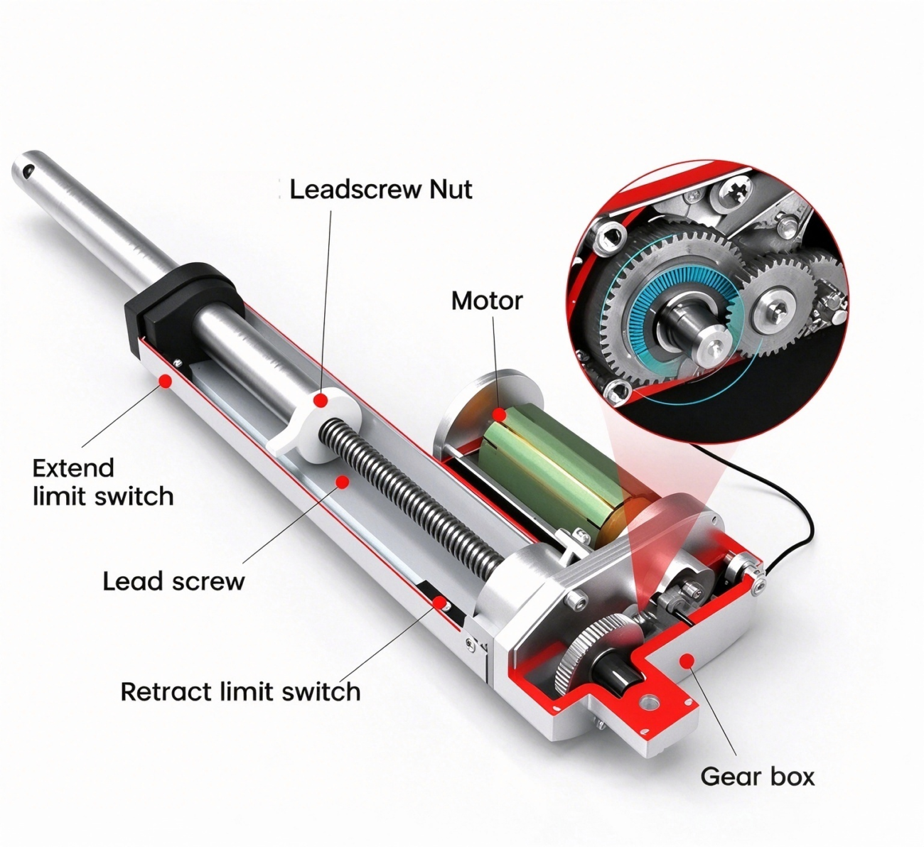
If you take apart a high-performance linear actuator used in a robot, you will usually find more than a motor and a screw.
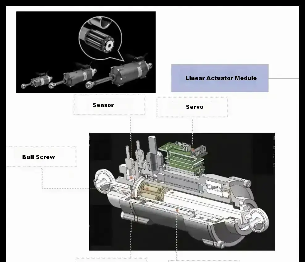
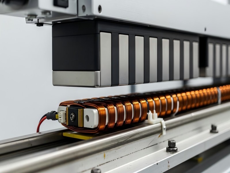
A typical unit contains a motor, a screw mechanism, bearings, position feedback, force sensing, and the mechanical structure that holds everything together. Depending on the design, the motor drive and control electronics may also be integrated into the actuator.
For humanoid robots, one common architecture can be simplified as:
Frameless Motor → Planetary Roller Screw → Linear Output
The motor generates rotary motion. The roller screw converts that rotation into axial movement and force. Bearings carry the loads, while encoders and force sensors provide the feedback required by the controller.
That sounds straightforward. In practice, fitting all of these parts into a small, lightweight joint while maintaining stiffness, efficiency, accuracy, and service life is where the engineering becomes difficult.
This article breaks down the main components of a robot linear actuator and explains what each part actually does.
1. Linear and Rotary Actuators: The Basic Difference
Most electromechanical joint actuators used in robots can be grouped into two basic architectures: rotary and linear.
A rotary actuator delivers torque directly to a rotating joint.
A linear actuator produces push-pull motion instead:
Motor → Screw Mechanism → Linear Output
This distinction is more useful than simply classifying actuators by motor type, because both architectures may use similar motors, encoders, bearings, and control electronics.
The major difference is the transmission.
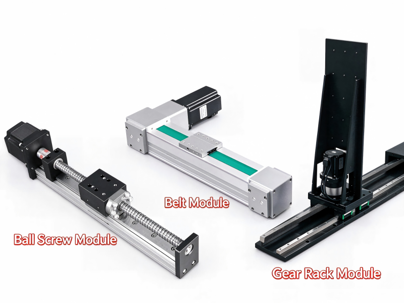
A rotary joint often uses a harmonic drive, planetary gearbox, or RV reducer. A linear actuator uses a screw mechanism such as a ball screw or planetary roller screw.
Typical Robot Actuator Architecture
Component
Rotary Actuator
Linear Actuator
Motor
Frameless motor
Frameless motor
Transmission
Harmonic / RV / planetary reducer
Ball screw / planetary roller screw
Output
Rotation
Linear displacement
Primary output
Torque
Axial force
Position feedback
Encoder
Encoder / linear position sensor
Load feedback
Torque sensing
Force sensing / force estimation
Support
Bearings
Bearings
Control
Servo drive
Servo drive
This table is only a general reference. There is no single actuator architecture used by every humanoid robot.
2. Frameless Motor: The Power Source
The motor is where the mechanical power starts.
In compact robot joints, engineers often use a frameless motor rather than a conventional packaged servo motor.
A frameless motor is supplied primarily as two electromagnetic assemblies:
Stator
Rotor
There is no conventional standalone motor housing and bearing arrangement. Instead, the motor is designed into the actuator itself.
This matters because packaging is a serious constraint in robotics.
If a complete housed motor is connected to a separate coupling, screw, bearing block, and sensor assembly, the resulting actuator can become unnecessarily long and heavy.
With a frameless design, the actuator housing can perform several jobs at once. It can support the bearings, locate the motor, provide mechanical interfaces, and help conduct heat away from the stator.
Why Use a Frameless Motor?
The practical advantages are mainly related to integration:
Shorter mechanical package
Lower unnecessary structural mass
High torque density
More freedom in shaft and bearing design
Better use of the available joint envelope
Greater flexibility in thermal design
There is a trade-off, however.
A frameless motor is not a drop-in component in the same way as a packaged servo motor. The actuator manufacturer has to solve rotor alignment, bearing support, air gap control, cooling, assembly tolerances, and encoder integration.
In other words, removing the motor housing saves space, but transfers more engineering responsibility to the actuator designer.
3. Planetary Roller Screw: Converting Rotation Into Linear Motion
For a high-force linear actuator, the screw mechanism is one of the most important parts of the system.
Its job is to convert motor rotation into controlled axial displacement.
Several screw technologies can perform this function:
Lead screws
Ball screws
Planetary roller screws
For compact, high-load robotic actuators, the planetary roller screw is particularly interesting.
How a Planetary Roller Screw Works
A planetary roller screw typically consists of a central screw, a nut, and multiple threaded rollers arranged around the screw.
Instead of transferring load through recirculating balls, as a ball screw does, the roller screw transfers load through the threaded contact between the screw, rollers, and nut.
The basic motion chain is:
Motor rotation → Screw/roller interaction → Axial displacement
The use of multiple rollers provides many load-carrying contact points within a relatively small diameter.
This makes the mechanism suitable for applications where high axial force has to be generated from a compact package.
Why Engineers Consider Roller Screws for Robot Actuators
The main reasons are:
High axial load capacity
High stiffness
High force density
Compact mechanical envelope
Precise motion
Good potential for long service life under appropriate operating conditions
But these benefits do not come for free.
Planetary roller screws are more difficult to manufacture than conventional lead screws, and their performance depends heavily on thread geometry, pitch accuracy, surface finish, heat treatment, material quality, and assembly.
A roller screw with poor manufacturing accuracy will not suddenly become a high-performance transmission simply because it uses rollers.
4. Planetary Roller Screw vs. Ball Screw
Ball screws and planetary roller screws perform the same basic job: converting rotary motion into linear motion.
The way they carry load is different.
A ball screw uses recirculating balls between the screw and nut. A planetary roller screw uses threaded rollers.
From an engineering standpoint, the choice should be based on the actuator requirements rather than on which technology sounds more advanced.
Parameter
Ball Screw
Planetary Roller Screw
Load transfer element
Ball
Threaded roller
Axial load capability
High
Very high in suitable designs
Stiffness
Good
High
Force density
Good
High
Manufacturing complexity
Lower
Higher
Cost
Generally lower
Generally higher
Availability
Mature supply chain
More specialized
Compact high-force applications
Good
Particularly suitable
A planetary roller screw therefore makes the most sense when the application can actually use its load density and stiffness.
For a lower-load mechanism, a ball screw may be the more practical solution.
This is an important point in robot design: the highest-specification component is not automatically the best component.
5. Bearings: Small Parts Carrying Large Loads
Bearings tend to disappear from actuator diagrams, but they are critical to the actual load path.
The motor creates torque. The screw converts that torque into axial force. That axial force has to react somewhere in the actuator structure.
The bearing arrangement provides that reaction path.
Depending on the design, bearings may need to handle:
Axial thrust
Radial load
Motor rotor support
Screw alignment
Overturning moments
For this reason, bearing selection cannot be separated from screw and housing design.
If the bearing arrangement has insufficient stiffness, the actuator may deflect under load even if the roller screw itself is extremely stiff.
Bearing preload also matters.
Too little preload can introduce unwanted axial movement. Too much preload increases friction, heat, and bearing load.
This is a typical actuator engineering trade-off: maximizing stiffness without creating excessive friction or reducing life.
6. Encoder: Knowing Where the Actuator Is
Generating motion is only half of the job.
The controller needs feedback.
An encoder measures the motor or screw position and provides information used by the servo control system.
Depending on the design, the actuator may use:
Incremental encoder
Absolute encoder
Magnetic encoder
Optical encoder
Rotary encoder
Linear position sensor
A rotary encoder mounted on the motor can infer linear displacement from screw lead.
For example, if the screw lead is known, one revolution of the screw corresponds to a defined amount of linear travel.
This approach is compact, but it measures motor/screw position rather than the actual output position.
Any compliance, backlash, or deformation between the measurement point and output can therefore affect the true position.
For applications requiring very accurate output-position feedback, a designer may add direct linear sensing.
7. Force and Torque Sensing
A common simplification is to say that every robot actuator contains a torque sensor.
That is not always correct, especially for linear actuators.
A rotary actuator naturally produces torque, while the useful output of a linear actuator is axial force.
Depending on the architecture, output load can be measured or estimated using:
Axial force sensors
Strain gauges
Load cells
Torque sensors
Multi-axis force/torque sensors
Motor current
Motor current is often useful because motor torque is related to current. With known transmission parameters, the controller can estimate output force.
However, estimated force and directly measured output force are not necessarily equivalent.
Friction, temperature, transmission efficiency, manufacturing variation, and wear can all affect the relationship between motor current and actual output load.
For applications requiring accurate contact-force control, direct sensing may therefore be valuable.
8. Housing and Mechanical Structure
The housing is not simply a cover around the actuator.
In an integrated design, it is part of the load-bearing structure.
It may provide:
Motor stator mounting
Bearing seats
Screw alignment
Joint mounting points
Sensor mounting
Heat conduction
Cable routing
Environmental protection
This is one reason actuator design cannot be optimized by selecting components independently.
A high-performance motor connected to a high-performance roller screw can still result in a poor actuator if the housing flexes, bearing seats are misaligned, or heat cannot escape from the motor.
The complete mechanical stack has to be treated as one system.
9. Motor Drive and Control Electronics
The motor requires a servo drive to control current and commutation.
Depending on the robot architecture, this electronics package may be located inside the actuator or elsewhere in the robot.
The control system typically works with several nested control loops.
At the lowest level, current control regulates motor torque. Higher-level loops can control velocity, position, or output force.
Feedback returns through the encoder and force-sensing system:
Encoder / Force Feedback → Controller → Correction
Mechanical and control design therefore influence each other.
Backlash, stiffness, friction, inertia, sensor resolution, and control bandwidth all affect how the actuator behaves.
10. How a Robot Linear Actuator Works
Putting the components together makes the operating sequence easier to understand.
The robot controller first requests a certain position, velocity, or force.
The motor drive supplies current to the frameless motor. The motor generates torque and rotates the screw mechanism.
The planetary roller screw then converts this rotation into axial movement.
That linear movement acts on the robot’s linkage or joint.
At the same time, the encoder reports position and velocity information. A force sensor—or a force estimate based on motor current—provides information about the actuator load.
The controller continuously compares the commanded state with the measured state and adjusts motor current accordingly.
So the complete energy and motion path is:
Electrical Power → Motor Torque → Screw Rotation → Linear Force and Motion
The feedback path runs in the opposite direction:
Position / Force Measurement → Controller → Motor Command
This closed-loop relationship is what turns a collection of mechanical components into a controllable robot actuator.
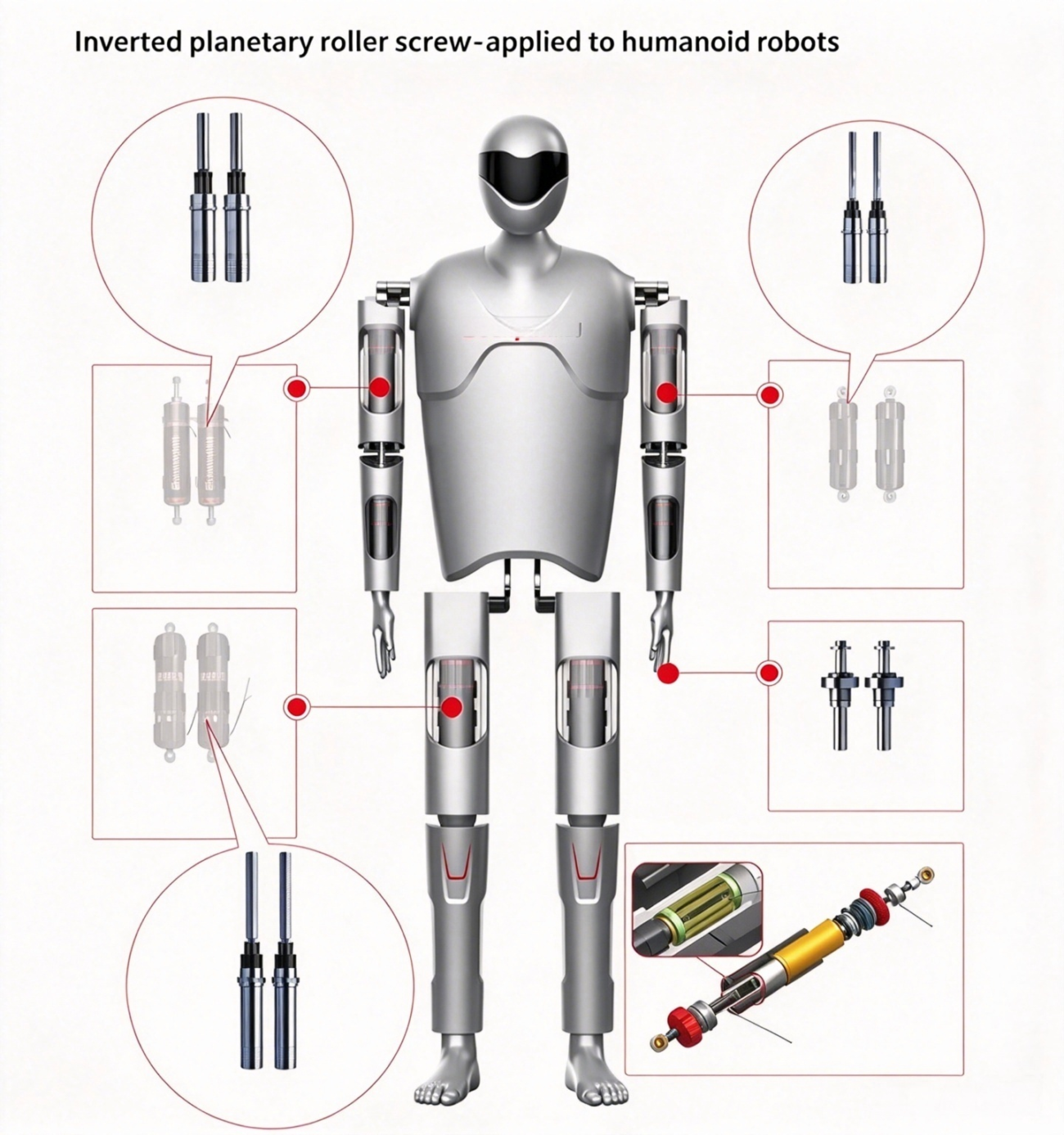
11. Linear Actuator vs. Rotary Actuator in Humanoid Robots
It is tempting to say that shoulders use rotary actuators while knees and ankles use linear actuators.
Actual robot designs are more complicated.
A knee joint, for example, can be driven directly by a rotary actuator. It can also be driven indirectly by a linear actuator acting through a linkage.
Neither approach is automatically better.
A designer has to consider:
Required joint torque
Joint speed
Range of motion
Available installation space
Actuator mass
Linkage geometry
Transmission efficiency
Impact loading
Backdrivability
Thermal limits
Cost
Serviceability
A linear actuator combined with a linkage can also create a variable mechanical advantage through the joint’s range of motion.
That can be useful in leg mechanisms where required joint torque changes significantly with joint angle.
On the other hand, the additional linkage introduces its own bearings, geometry, packaging constraints, and possible losses.
The actuator therefore has to be evaluated as part of the complete robot mechanism—not as an isolated component.
12. What Actually Determines Linear Actuator Performance?
Maximum force is usually the first number people look at.
It should not be the only one.
For robot applications, useful actuator specifications include:
Continuous Force
The force the actuator can sustain without exceeding its thermal or mechanical limits.
Peak Force
The short-duration force available for acceleration, impacts, or other transient loads.
Stroke
The available linear travel.
Speed
The maximum and continuous linear velocity.
Force Density
How much force can be generated for a given actuator mass or volume.
Lost motion when the direction of load or movement reverses.
Efficiency
The amount of motor power that reaches the mechanical output.
Thermal Performance
How quickly heat is generated and how effectively it can leave the actuator.
Service Life
The expected operating life under the actual load spectrum and duty cycle.
These parameters interact.
Increasing screw lead, for example, changes the relationship between motor speed, linear speed, and required motor torque.
Increasing preload may improve stiffness and reduce free play but also increases friction.
Making components larger may increase load capacity but also increases actuator mass and inertia.
There is rarely a single specification that can be maximized without affecting another.
13. The Real Engineering Challenge Is Integration
The individual components of a linear actuator are not difficult to list:
Motor + Roller Screw + Bearings + Encoder + Force Sensing + Housing + Control
The difficult part is making them work together.
A motor with excellent torque density is of limited value if it overheats inside the actuator.
A high-capacity roller screw does not solve the problem if the bearings or housing deform under the same load.
A high-resolution encoder cannot compensate for excessive mechanical compliance.
And an actuator capable of impressive peak force may still be unsuitable for a robot if it cannot sustain the required duty cycle.
For humanoid robots in particular, actuator development is largely an exercise in balancing:
Force, speed, stiffness, mass, volume, efficiency, temperature, life, and cost.
Improving one often affects several others.
That is why actuator performance should be evaluated at the system level rather than by comparing a single component specification.
Frequently Asked Questions
What are the main components of a linear actuator?
A high-performance electromechanical linear actuator typically consists of a motor, screw transmission, bearings, position sensing, force sensing, housing, and control electronics.
For some humanoid robot designs, the combination of a frameless motor and planetary roller screw provides a compact way to generate high linear force.
What does the roller screw do in a linear actuator?
The roller screw converts rotary motion from the motor into linear displacement and axial force.
It is the primary mechanical transmission between the motor and the actuator output.
Why use a planetary roller screw instead of a ball screw?
Planetary roller screws can provide high axial load capacity, stiffness, and force density in a compact package.
Ball screws, however, are generally simpler and more widely available. The correct choice depends on load, speed, stroke, life, packaging, and cost requirements.
What is the main difference between a linear actuator and a rotary actuator?
The difference is the mechanical output.
A rotary actuator outputs angular displacement and torque. A linear actuator outputs linear displacement and axial force.
The transmission reflects this difference: rotary actuators generally use gear reduction, while electromechanical linear actuators use screw mechanisms or other rotary-to-linear transmissions.
Do all humanoid robot joints use linear actuators?
No.
Humanoid robots can use rotary actuators, linear actuators, or a combination of both. The architecture depends on joint geometry, force and torque requirements, speed, packaging, weight, efficiency, and control strategy.
What are the most important specifications when selecting a robot linear actuator?
Start with continuous and peak force, stroke, linear speed, stiffness, efficiency, actuator mass, duty cycle, thermal limits, and expected service life.
For a robot joint, these parameters should be evaluated together rather than independently.
Conclusion
A robot linear actuator is not simply a motor connected to a screw.
It is an integrated electromechanical system in which the motor generates torque, the screw converts that torque into linear force, the bearings establish the load path, sensors provide position and load feedback, and the housing keeps the entire assembly aligned and mechanically stiff.
For a planetary roller screw actuator, the basic architecture can be reduced to:
Frameless Motor → Planetary Roller Screw → Linear Output
with:
Bearings + Encoder + Force Sensing + Housing + Control
built around that power-transmission chain.
Understanding this structure also explains why designing a compact humanoid robot actuator is difficult. The challenge is not simply achieving the highest possible force.
The actuator has to produce the required force and speed within a limited mass and volume, maintain sufficient stiffness and positioning accuracy, control heat, survive the required duty cycle, and remain economically manufacturable.
That system-level balance is what ultimately determines whether a linear actuator works well in a real robot.
HCY Automation delivers integrated solutions across motion control, linear motion, robotics, machine vision, pneumatic systems, and precision gearboxes to help global manufacturers build smarter, faster, and more reliable production lines. Our engineering team helps you select and integrate the right motion control, robotics, and automation components for your specific application.