What Is a Linear Motor Stage? Working Principle, Benefits & Applications
Learn how linear motor stages work, their key components, advantages over ball screw stages, and applications in precision automation and motion control.
In precision automation, moving a component from point A to point B is rarely the difficult part. The real challenge is moving it quickly, stopping at the correct position, and repeating the same motion thousands of times without losing accuracy.
Unlike conventional motion systems that convert rotary motion into linear travel through a ball screw or belt, a linear motor stage uses electromagnetic force to drive the moving carriage directly. This eliminates the need for a mechanical transmission between the motor and the load.
The result is a motion system capable of high acceleration, smooth velocity control, and precise positioning.
But how does a linear motor stage actually work? What makes it different from a traditional linear actuator? And when does direct-drive technology make sense for industrial equipment?
Let’s look at the engineering behind it.
What Is a Linear Motor Stage?
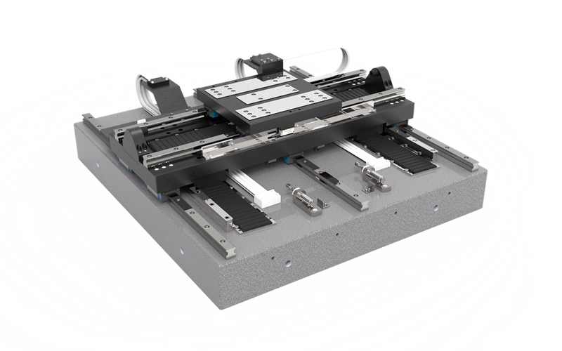
A linear motor stage is a precision motion control system that uses a linear electric motor to move a carriage along a straight path without a ball screw, belt, or other rotary-to-linear transmission.
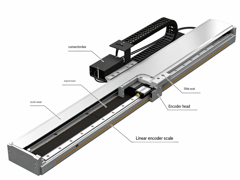
A typical linear motor positioning stage consists of four essential elements:
Linear motor: Generates electromagnetic thrust to move the carriage directly.
Linear guide system: Supports the moving load and maintains the required straightness and mechanical stability.
Linear encoder: Measures the actual carriage position and provides feedback to the controller.
Servo drive and motion controller: Regulate current, velocity, and position to execute the commanded motion.
These components work together to provide accurate, repeatable movement.
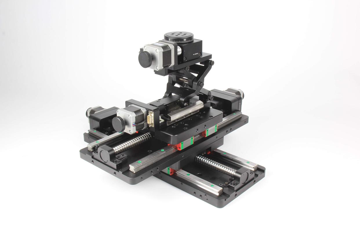
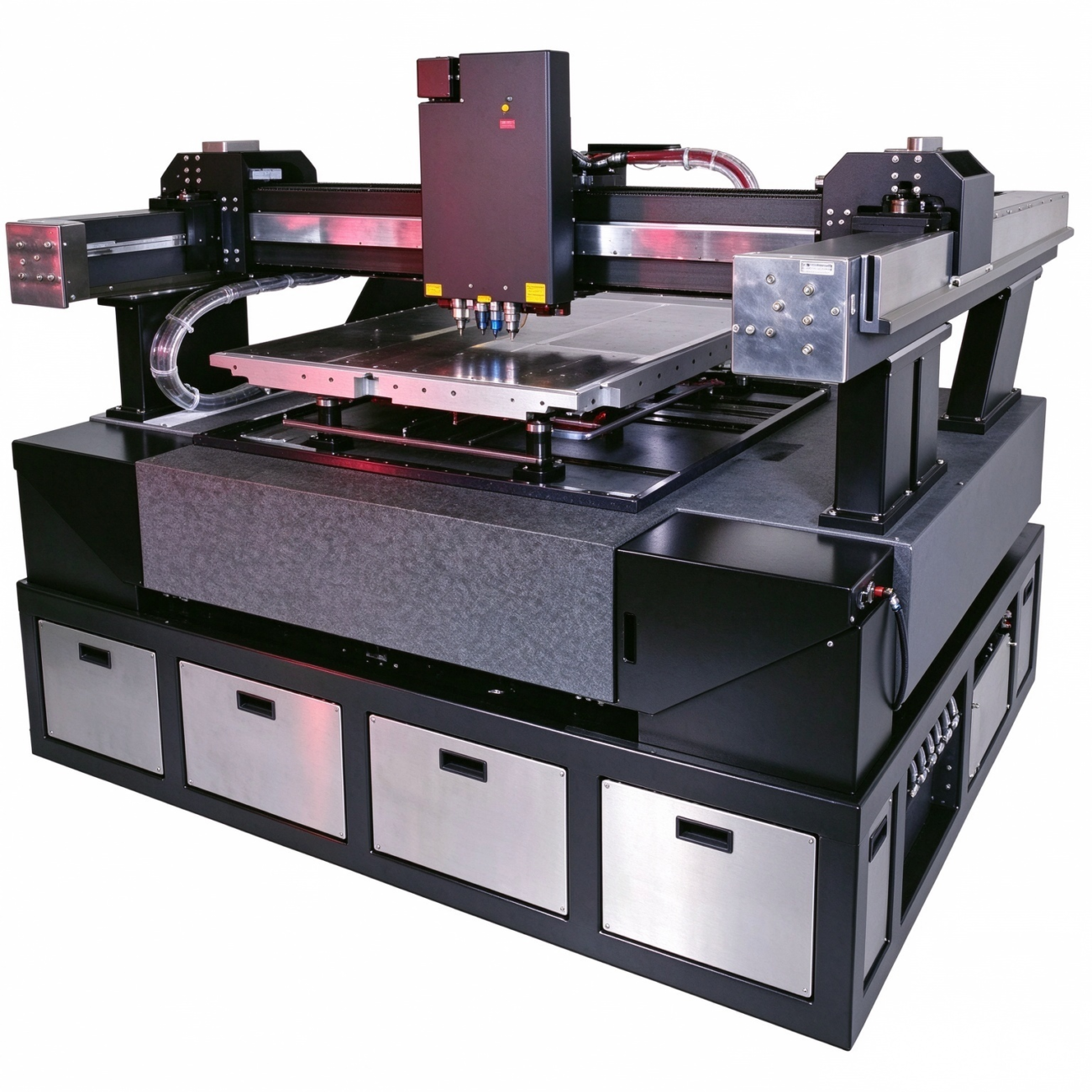
Depending on the application, linear motor stages can be configured as single-axis positioning systems or integrated into multi-axis arrangements such as XY, XYZ, and XYθ motion platforms.
They are widely used in semiconductor equipment, machine vision inspection, laser processing, electronics manufacturing, and other applications where dynamic performance matters as much as positioning accuracy.
How Does a Linear Motor Stage Work?
The basic principle is electromagnetic force.
A linear motor can be understood as a rotary electric motor that has been conceptually unrolled into a straight line. Instead of producing rotational torque, it generates thrust along a linear path.
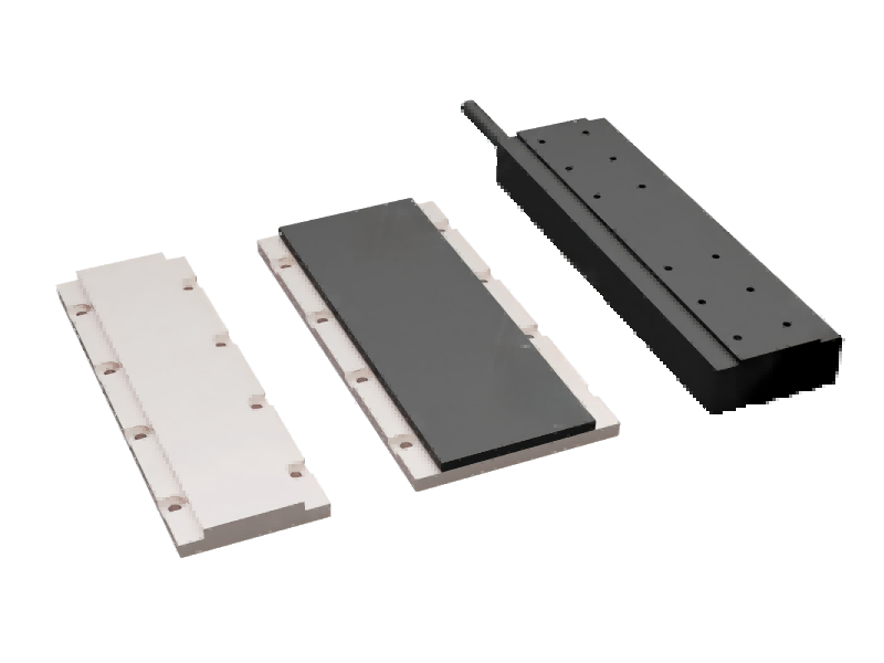
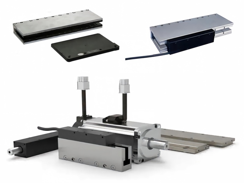
In a common brushless linear servo motor design, the main components are a permanent-magnet track and an electromagnetic coil assembly.
When controlled current flows through the coils, the resulting magnetic field interacts with the magnetic field of the permanent magnets. This interaction produces force in the direction of travel.
By controlling the phase and magnitude of the coil currents, the servo drive regulates the motor’s movement.
Because the motor produces linear force directly, the stage does not require a rotating screw or mechanical transmission to move the carriage.
How the Closed-Loop Control System Works
For precision positioning, generating thrust is only part of the process. The controller also needs to know where the carriage is located.
A typical closed-loop motion sequence works as follows:
The motion controller sends a target position or motion profile.
The servo drive supplies controlled current to the linear motor.
Electromagnetic thrust moves the carriage along the linear guides.
The linear encoder continuously measures the carriage position.
The controller compares the measured position with the commanded position and adjusts the motor current to reduce tracking error.
This feedback process allows the system to control position, velocity, and acceleration throughout the motion cycle.
With an appropriate encoder, rigid mechanical structure, and properly tuned servo system, a linear motor stage can achieve micron-level or submicron-level positioning performance.
However, actual accuracy depends on the complete system design rather than the motor alone.
Key Components of a Linear Motor Stage
Understanding the components is useful when evaluating a linear motion system for a new machine design.
1. Linear Servo Motor
The linear servo motor is responsible for generating thrust.
Two common configurations are iron-core and ironless linear motors.
Iron-core linear motors generally provide high force density and are useful for moving heavier loads or applications requiring high thrust. However, magnetic attraction and cogging effects must be considered during system design.
Ironless linear motors eliminate iron-related cogging in the moving coil assembly and can provide exceptionally smooth low-speed motion. They are often selected for inspection, scanning, and other precision applications.
The choice between these two motor designs depends on required force, load capacity, velocity stability, thermal behavior, and available installation space.
2. Linear Guide System
Although the linear motor operates without mechanical contact between its electromagnetic moving and stationary parts, most industrial stages still use mechanical linear guides.
These guides support the carriage, resist external loads, and maintain alignment during travel.
Guide straightness, preload, installation accuracy, and structural rigidity directly affect the overall motion performance.
For applications requiring extremely smooth movement, an air-bearing system may be used instead of conventional rolling-element guides.
3. Linear Encoder
A linear encoder provides direct position feedback.
Unlike systems that estimate linear position from motor rotation, a linear encoder measures movement along the actual travel axis.
Common feedback technologies include optical and magnetic linear encoders.
For demanding precision applications, the choice of encoder should consider:
Measurement resolution
Absolute positioning accuracy
Signal stability
Environmental resistance
Thermal expansion
Installation alignment
One important engineering distinction is that encoder resolution is not the same as stage positioning accuracy.
A high-resolution encoder cannot fully compensate for mechanical deformation, poor guide alignment, thermal drift, or inadequate servo tuning.
4. Servo Drive and Motion Controller
The servo drive regulates motor current and performs closed-loop motion control, while the motion controller generates commands for positioning, scanning, and coordinated movement.
Depending on the system architecture, these functions may be integrated.
Advanced motion control systems can support point-to-point positioning, coordinated multi-axis movement, electronic synchronization, and continuous-path motion.
Proper tuning is especially important in direct-drive systems because there is no mechanical transmission to isolate the motor from load disturbances.
Why Use a Linear Motor Stage?
The main advantage of a linear motor stage is not simply that it moves faster.
Its value comes from combining direct-drive motion with precise feedback control.
High Speed and Acceleration
Traditional screw-driven systems are affected by screw rotational inertia, critical speed, and transmission dynamics.
A direct-drive linear motor removes many of these constraints, allowing higher speeds and accelerations when the mechanical structure and motor sizing support them.
This is particularly valuable in high-throughput inspection machines, semiconductor handling equipment, and repetitive pick-and-place operations.
No Mechanical Transmission Backlash
Backlash occurs when mechanical clearance produces lost linear motion during a change in direction.
Because a linear motor stage does not use a screw or gearbox in its drive path, mechanical transmission backlash is eliminated.
This improves motion reversals and helps maintain positioning consistency during high-frequency operating cycles.
High Positioning Repeatability
With accurate feedback and appropriate system design, a linear motor stage can return repeatedly to the same commanded position with very small variation.
This is useful for precision assembly, machine vision inspection, laser processing, and measurement equipment.
It is important to distinguish repeatability from absolute positioning accuracy. A system can repeat a position consistently while still having an offset from its intended location.
Smooth Velocity Control
Linear motors are well suited to applications requiring stable motion at controlled speeds.
Smooth velocity is particularly important during optical inspection, surface scanning, laser processing, and continuous measurement.
Reducing velocity fluctuations can improve imaging consistency and process quality.
Reduced Transmission Maintenance
A linear motor does not require lubrication or maintenance of a ball screw, belt, or gearbox in its drive system.
This reduces the number of mechanical transmission components subject to wear.
However, the complete stage is not necessarily maintenance-free. Linear guides, cable carriers, seals, cooling components, and feedback systems still require appropriate inspection.
Linear Motor Stage vs. Ball Screw Stage: What’s the Difference?
Both technologies are widely used in industrial automation, but they solve different motion control challenges.
Feature
Linear Motor Stage
Ball Screw Stage
Drive mechanism
Direct electromagnetic drive
Rotary motor with ball screw
Mechanical transmission
No screw or belt required
Ball screw and nut required
Speed potential
Generally higher
Limited by screw and system design
Acceleration potential
High
Dependent on rotational inertia and load
Transmission backlash
Eliminated
Can be minimized through preloading
Position feedback
Commonly uses a linear encoder
May use rotary or linear feedback
Maintenance
Lower transmission maintenance
Screw lubrication and inspection required
Initial investment
Generally higher
Often more economical
Best applications
High-speed, high-precision dynamic motion
General positioning and high-thrust applications
When Is a Linear Motor Stage the Better Choice?
Consider a direct-drive linear motor stage when your application requires:
Frequent acceleration and deceleration
Fast point-to-point positioning
Smooth constant-velocity scanning
High positioning repeatability
High cycle rates
Minimal transmission backlash
Reduced mechanical transmission wear
When Does a Ball Screw Stage Make More Sense?
A ball screw stage may be the more practical solution when the application has moderate speed requirements, a limited budget, or requires high mechanical thrust.
Ball screw systems can also be advantageous for certain vertical-axis applications, depending on the holding and braking requirements.
The correct selection depends on the load, motion profile, travel length, operating environment, accuracy requirements, and total system cost.
Engineering takeaway: A linear motor is not automatically the best choice for every precision machine. Direct drive becomes most valuable when dynamic motion performance justifies its additional system cost and design requirements.
Where Are Linear Motor Stages Used?
Linear motor stages are used wherever manufacturers need a combination of speed, repeatability, and controlled motion.
Semiconductor Manufacturing and Inspection
Semiconductor processes demand accurate motion, stable scanning, and repeatable positioning.
Linear motor stages can be found in wafer inspection systems, probe equipment, semiconductor handling systems, and precision alignment applications.
Depending on the machine architecture, they may be integrated into multi-axis positioning platforms.
For particularly demanding semiconductor equipment, thermal stability, vibration isolation, and precision feedback become critical design considerations.
Laser Cutting, Marking, and Micromachining
In laser processing equipment, motion quality has a direct effect on the finished part.
Linear motor stages can provide smooth movement and rapid direction changes, making them suitable for fine-feature laser cutting, micro-drilling, engraving, and precision laser processing.
For continuous-path operations, stable velocity and accurate trajectory tracking are often more important than maximum travel speed alone.
Machine Vision and Optical Inspection
Automated inspection systems frequently require cameras, sensors, or products to travel along a controlled path.
A linear motor positioning stage can provide consistent scanning velocity and repeatable movement.
Typical applications include PCB inspection, display inspection, dimensional measurement, surface defect detection, and optical scanning.
Precision Assembly and Electronics Manufacturing
Electronic components are becoming smaller, while automated production lines continue to demand higher throughput.
Linear motor stages can support precision dispensing, component alignment, small-part assembly, and high-speed positioning.
They are especially useful when a machine must combine fast transfer motion with precise settling at the target position.
Medical Devices and Laboratory Automation
Medical and laboratory equipment often requires controlled motion with repeatable positioning.
Linear motor stages can be integrated into imaging equipment, sample handling platforms, automated testing systems, and precision laboratory instruments.
The mechanical design, materials, and control strategy must be selected according to the specific equipment environment and applicable regulatory requirements.
Single-Axis, XY, and XYZ Linear Motor Stages
Linear motor stages can be configured in several ways depending on the motion requirements.
Single-Axis Linear Motor Stage
A single-axis system provides movement along one straight line.
It is commonly used for product transfer, scanning, positioning, and machine-axis motion.
XY Linear Motor Stage
An XY stage combines two perpendicular linear axes to provide two-dimensional positioning.
This configuration is widely used in machine vision, inspection systems, laser processing, and precision alignment.
XYZ Linear Motor Stage
An XYZ stage adds a vertical axis to create three-dimensional positioning capability.
It is commonly used in assembly, metrology, semiconductor equipment, and automated manufacturing systems.
XYθ Motion Stage
An XYθ stage combines X-axis and Y-axis movement with rotational positioning.
This arrangement is useful for applications requiring both linear alignment and angular correction, such as optical alignment and precision assembly.
In multi-axis systems, overall performance depends on more than individual axis accuracy. Structural stiffness, axis squareness, cable forces, controller synchronization, and vibration also need to be considered.
How to Choose the Right Linear Motor Stage
Choosing a linear motor stage starts with defining the machine’s actual motion requirements.
A motor with a high peak thrust rating may look impressive on paper, but it will not necessarily provide the best performance in the finished equipment.
The following parameters should be evaluated before making a selection.
1. Travel Stroke
Determine the required travel distance, including any clearance needed for acceleration, deceleration, and mechanical limits.
A longer stroke may influence the magnetic track length, encoder selection, cable management, and overall machine footprint.
2. Payload Capacity
Calculate the total moving mass, including the workpiece, fixture, carriage-mounted components, and any additional moving hardware.
Payload also affects guide selection, settling time, and structural deflection.
3. Maximum Speed and Acceleration
Define the actual motion profile rather than relying only on maximum speed.
For example, an application with a short travel distance may never reach the motor’s rated maximum velocity.
In such cases, acceleration and settling time may have a greater influence on cycle time.
4. Positioning Accuracy and Repeatability
Specify the accuracy required at the working point.
Review the difference between encoder resolution, unidirectional repeatability, bidirectional repeatability, and absolute positioning accuracy.
For high-precision systems, establish an error budget covering the mechanical structure, feedback device, temperature, and control system.
5. Motor Thrust and Duty Cycle
Both peak force and continuous force must be considered.
For a simplified horizontal axis, the acceleration force can be estimated as:
F = m × a
Where:
F = Required acceleration force (N)
m = Total moving mass (kg)
a = Required acceleration (m/s²)
Additional forces from friction, cable drag, external process loads, and operating conditions must also be included.
Continuous operation requires thermal evaluation based on the actual duty cycle, not just peak thrust.
6. Installation and Thermal Management
Mounting-surface flatness, guide alignment, and mechanical rigidity are critical for precision positioning.
Linear motors also generate heat. Depending on the motor design and duty cycle, thermal expansion may affect the stage structure, encoder system, and workpiece.
For high-duty-cycle or high-precision equipment, cooling, temperature monitoring, and thermal compensation may be necessary.
7. Environmental Conditions
Consider whether the stage will operate in a cleanroom, industrial production line, laboratory, or other controlled environment.
Dust, coolant, electromagnetic interference, temperature fluctuations, and mechanical vibration can influence component selection and long-term performance.
Common Engineering Mistakes to Avoid
When evaluating a linear motor stage, several assumptions can lead to disappointing results.
Mistake 1: Treating encoder resolution as positioning accuracy.
A nanometer-resolution encoder does not automatically make the entire stage accurate to a nanometer. Guide geometry, thermal expansion, alignment, and feedback control all affect the actual position.
Mistake 2: Selecting a motor based only on maximum speed.
For short-stroke, repetitive motion, acceleration, deceleration, and settling time may determine the achievable cycle time.
Mistake 3: Ignoring thermal behavior.
Motor heating and environmental temperature changes can cause dimensional shifts that become significant in micron-level positioning systems.
Mistake 4: Assuming direct drive means zero maintenance.
The motor eliminates transmission-related wear, but guide systems and other mechanical components still require maintenance.
Mistake 5: Overlooking the full mechanical system.
A high-performance motor cannot compensate for a flexible machine frame, poorly installed guides, or an unstable payload.
The most reliable designs consider the motor, feedback system, mechanical structure, and control parameters together.
Frequently Asked Questions About Linear Motor Stages
What is a linear motor stage used for?
A linear motor stage is used for precise linear positioning, high-speed transfer, smooth scanning, and repetitive motion in automated machinery. Common applications include semiconductor inspection, laser processing, machine vision, precision assembly, and laboratory automation.
How accurate is a linear motor stage?
Accuracy depends on the encoder, guide system, mechanical structure, temperature, calibration, and controller performance. Well-designed systems can achieve micron-level or submicron-level positioning, but the actual specification must be verified for the complete stage.
What is the difference between a linear motor and a linear actuator?
A linear motor directly generates electromagnetic thrust. A linear actuator is a broader category of devices that produce linear movement and may use ball screws, belts, pneumatic cylinders, or other mechanisms. A linear motor stage is a positioning assembly that uses a linear motor as its drive source.
Is a linear motor stage better than a ball screw stage?
It depends on the application. Linear motor stages are often preferred for high acceleration, high-speed scanning, and dynamic precision positioning. Ball screw stages remain practical for many moderate-speed, high-thrust, and cost-sensitive applications.
Does a linear motor stage require lubrication?
The electromagnetic motor itself does not require transmission lubrication. However, stages equipped with rolling-element linear guides may still require lubrication according to the guide manufacturer’s specifications.
Can a linear motor stage be used for vertical motion?
Yes, but a vertical-axis linear motor stage requires special attention to gravity loads and power-loss safety. A suitable brake, counterbalance, or other safety mechanism may be necessary to prevent uncontrolled movement when motor power is removed.
Can linear motor stages be customized?
Yes. Depending on the design, parameters such as travel stroke, payload capacity, motor configuration, encoder feedback, mounting arrangement, and multi-axis integration can be adapted to the application.
Final Thoughts
A linear motor stage offers a practical way to achieve fast, controlled, and highly repeatable linear motion without the mechanical transmission used in conventional screw- or belt-driven systems.
Its direct-drive structure can improve dynamic response, reduce transmission backlash, and support stable motion at high operating speeds.
However, the real performance of a precision positioning stage depends on the complete mechanical and control system. Motor thrust, encoder feedback, guide accuracy, thermal management, and machine rigidity must all work together.
For semiconductor equipment, optical inspection, laser processing, and precision automation, linear motor stages can provide significant advantages where speed and motion quality are critical.
Planning a precision motion application?
Start with the required travel stroke, moving mass, maximum speed, acceleration, positioning accuracy, and duty cycle. These specifications provide the foundation for selecting a suitable linear motor stage and avoiding unnecessary cost or performance limitations.
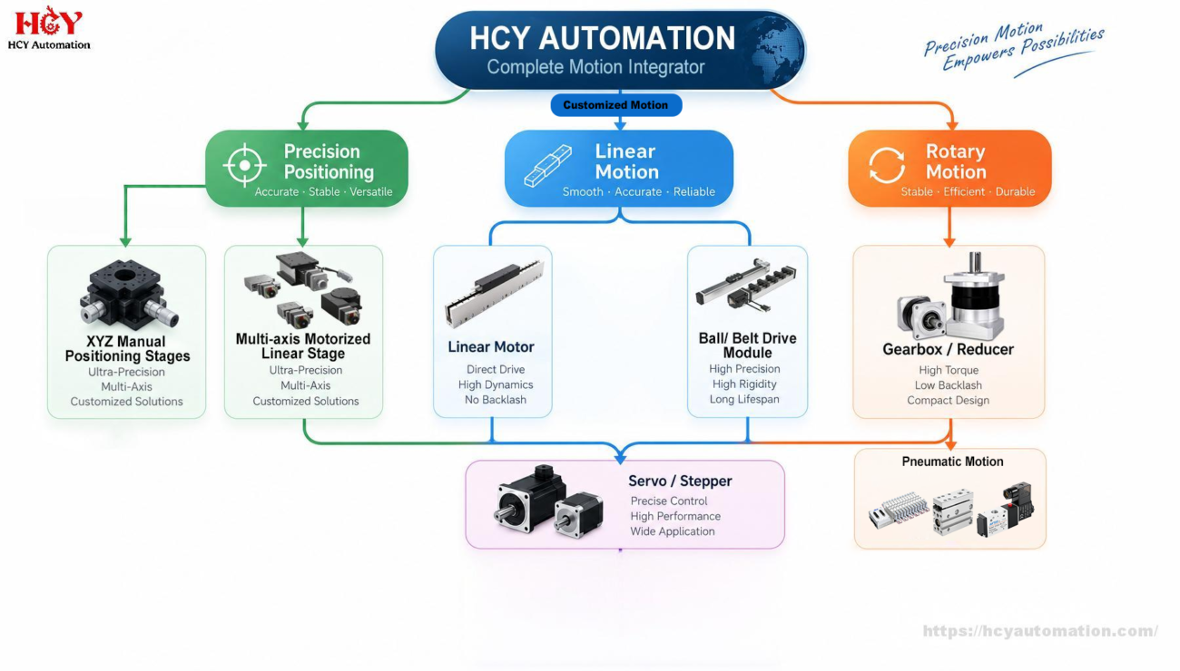
HCY Automation, we provide customized linear motors and precision linear motor stages designed to meet the specific needs of industrial automation, semiconductor equipment, machine vision inspection, laser processing, and precision manufacturing.
HCY Automation delivers integrated solutions across motion control, linear motion, robotics, machine vision, pneumatic systems, and precision gearboxes to help global manufacturers build smarter, faster, and more reliable production lines. Our engineering team helps you select and integrate the right motion control, robotics, and automation components for your specific application.