What is a fiber alignment stage? HCY Automation In Stock & Ready to Ship
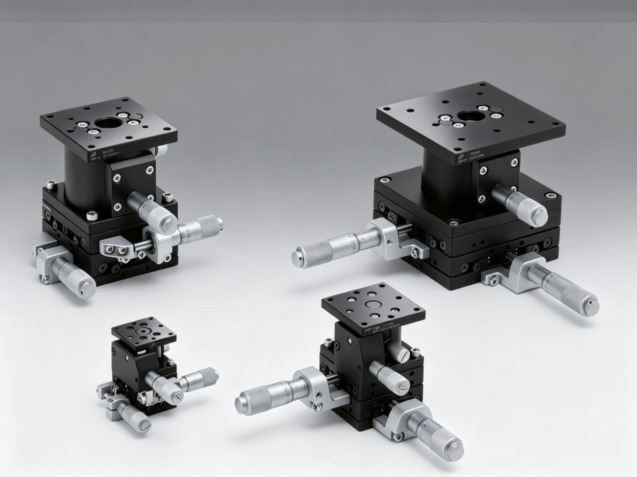
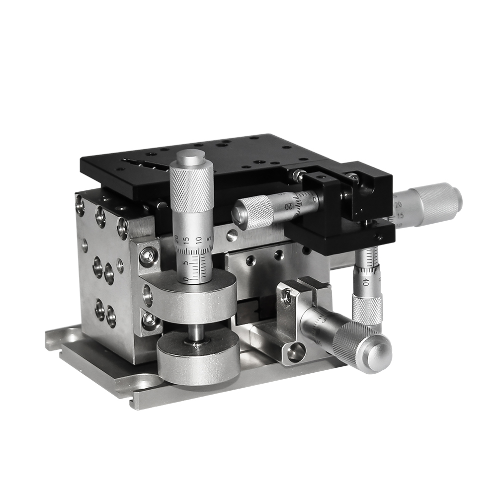
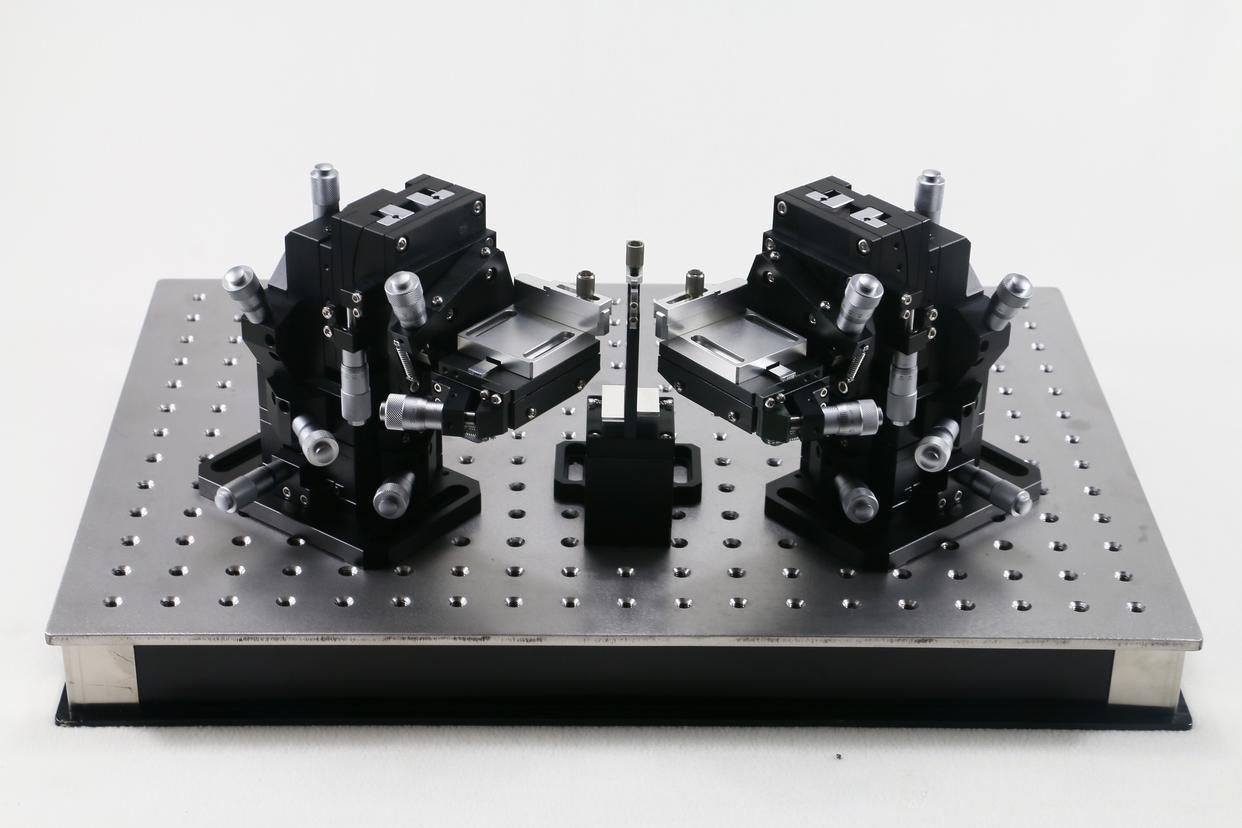
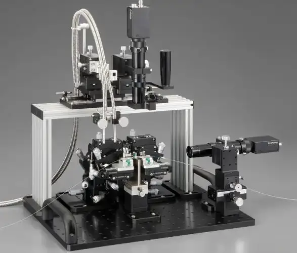
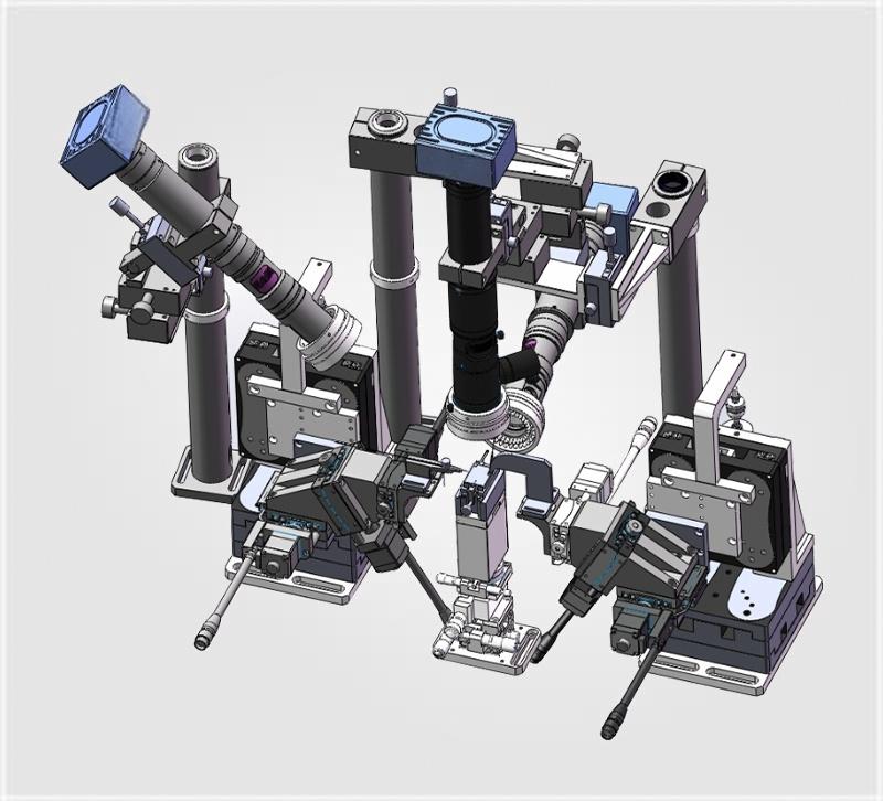
A fiber alignment stage — also called a fiber-optic alignment stage, fiber-coupling stage, or photonics positioning stage — is a precision motion-control platform designed to align optical fibers, waveguides, lenses, and photonic integrated circuits (PICs) with accuracies routinely measured insub-micron or even nanometer scales.
Unlike general-purpose translation stages, fiber alignment stages are engineered for:
High-resolution travel – typically 6 mm to 150 mm per axis with encoder resolutions down to 1 nm.
Low drift & thermal stability – critical for long-duration wafer probing or laser-diode burn-in.
Vibration isolation compatibility – because a 50 nm misalignment can drop coupling efficiency by 3 dB.
Automation readiness – USB, Ethernet, or RS-232 interfaces for integration into Python / LabVIEW / MATLAB control stacks.
It is designed to achieve micro-level precise position and angle adjustment between optical elements: single-mode/multimode optical fibers, fiber arrays, photonic integrated chips, waveguides, laser diodes, collimating lenses and optical transceivers.
The mainstream standard fiber alignment stage adopts a 6-axis configuration:
3 linear axes (X, Y, Z): Complete coarse spatial displacement positioning
Based on driving modes, fiber alignment stages are divided into three core categories:
Manual fiber alignment stage: Driven by micrometer heads, low cost, flexible operation, mainly used for university laboratories, small prototype verification and low-volume optical coupling tests.
Motorized fiber alignment stage: Driven by precision motors, supports programmable automatic alignment, compatible with EtherCAT and other industrial bus control, suitable for automated mass production of optical packaging and high-throughput wafer testing.
Choose based on automation need, EMI sensitivity and throughput target
Ideal Use Case Summary
Precision static alignment where EMI-free, low-cost and compact manual tuning is prioritized
Dynamic, high-throughput, programmable positioning where speed and repeatability dominate
—
Typical Application Scenarios
Optical Transceiver Packaging: Aligning laser diodes with fiber arrays before epoxy curing or laser welding.
Silicon Photonic Chip Testing: Precisely coupling optical fibers to the waveguide ports on a photonic integrated circuit (PIC).
Laser Diode Alignment: Adjusting the distance between a lens and an optical fiber to optimize beam coupling efficiency.
Quantum Optics Experiments: Maintaining nanometer-scale stability in cryogenic environments.
5G / Data Center Deployment: Rapid on-site fiber connection and field installation.
Core Pain Point for Global Buyers: Long Lead Time of Precision Alignment Equipment
Most manufacturers of optical motion positioning equipment have long production cycles for standard fiber alignment stages, often requiring 4–12 weeks of lead time. For urgent prototype verification, short pilot production cycles and time-sensitive lab projects, long waiting periods will delay the whole project schedule.
To solve this industry bottleneck, HCY Automation keeps a full range of standard fiber alignment stages in stock, ready for immediate shipment worldwide.
The Invisible Hero Behind Every AI Data Center
If you have ever wondered how terabits of data flow seamlessly between thousands of GPUs in an AI training cluster, the answer is not just in the chips — it is in the fiber alignment stage.
A fiber alignment stage (also called a fiber-optic alignment stage, fiber-coupling stage, or photonics positioning platform) is a precision motion-control device that positions optical fibers, waveguides, lenses, and photonic integrated circuits (PICs) with accuracies measured in sub-micron or even nanometer scales. Without it, the optical signals that power 800G transceivers, silicon-photonic chips, and 5G fronthaul networks would simply fail to couple.
In 2026, as the global optical interconnect for AI market surges toward $38.4 billion by 2034 (growing at 18.1% CAGR), fiber alignment stages have moved from niche lab equipment to critical-path infrastructure. The problem? Lead times for high-precision stages now stretch 12–26 weeks, and procurement teams are scrambling.
That is why “In Stock & Ready to Ship” has become the most valuable specification in photonics procurement this year.
How to Choose the Right Fiber Alignment Stage for Your Application
Step 1: Define Your Precision Budget
Application
Required Precision
Recommended Stage Type
Telecom component test
±0.5 µm
Motorized XYZ
Silicon photonics wafer probing
±50 nm
Piezo or 6-DOF motorized
Quantum optics / cryogenic
±10 nm
Piezo with thermal compensation
Fiber laser assembly
±1 µm
Motorized XYZ + tip/tilt
Step 2: Match Travel Range to Your Device Geometry
Single-fiber pigtailing → 25 mm × 25 mm × 25 mm XYZ is typical
Fiber array to PIC edge coupling → 100 mm+ travel on one axis for wafer-scale probing
Free-space to fiber coupling → Tip/tilt (θx, θy) stages are essential; look for arc-second resolution
Step 3: Prioritize Throughput vs. Resolution
High-volume production → Fast servo motors, 500+ UPH (units per hour), integrated vision
R&D / NPI → Manual or semi-automated stages with maximum flexibility
Step 4: Verify Software & API Compatibility
Modern stages should ship with:
Native Python SDK
NI LabVIEW VIs
MATLAB instrument driver
EtherCAT or REST API for Industry 4.0 integration
Step 5: Confirm Environmental Ratings
Cleanroom (Class 100–1000) → Anodized aluminum with minimal particulate generation
Vacuum (< 10⁻⁶ mbar) → Outgassing-tested materials; avoid standard greases
Cryogenic (4 K) → Piezo-walk or cryo-rated stepper motors; verify datasheet specs at temperature
Active vs. Passive Alignment: Which One Do You Need?
Method
How It Works
Coupling Efficiency
Speed
Cost
Passive Alignment
Mechanical fiducials and tolerances
Lower (typically 1–2 dB loss)
Fast
Lower
Active Alignment
Real-time optical feedback (power meter, camera, spectrometer) optimizes position before epoxy cure or laser weld
Higher (2–4 dB improvement)
Slower
Higher
Active alignment is now the standard for high-performance 800G/1.6T transceivers and silicon-photonic devices. It requires a motorized or piezo stage with closed-loop feedback and software integration — exactly the category where HCY Automation maintains ready-to-ship inventory.
Regional Demand Snapshot: Where the Bottleneck Is Worst
Region
Market Share
Growth Driver
Inventory Urgency
Asia-Pacific
41.3%
China silicon-photonics fabs, South Korea 5G, Japan R\&D
Critical — local stock preferred to avoid customs delays
North America
29.8%
AI data centers, DoD photonics, quantum labs
Very High — CHIPS Act funding accelerating builds
Europe
21.0%
Automotive LiDAR, telecom infrastructure
High — sustainability mandates favor durable hardware
Rest of World
7.9%
Emerging telecom, academic labs
Growing
Emerging Trends Reshaping the Fiber Alignment Stage Market
AI-Enhanced Active Alignment
Machine-learning algorithms are now being embedded into alignment controllers to predict drift, compensate for thermal transients, and reduce alignment cycle times by up to 60%. Vendors offering AI-ready firmware are seeing faster adoption in high-volume PIC assembly.
Miniaturization for Co-Packaged Optics (CPO)
The push for CPO is driving demand for ultra-compact stages that fit inside transceiver form factors. Some suppliers now offer “alignment-on-chip” micro-positioners with MEMS actuators.
Wireless Control & Remote Monitoring
Post-pandemic, remote diagnostics have become standard. Stages with Wi-Fi / Bluetooth connectivity allow engineers to monitor alignment stability from anywhere — a valued feature for 24/7 production lines.
Sustainability & Circular Economy
European buyers increasingly ask for repairable actuators, recyclable aluminum housings, and energy-efficient controllers. Suppliers with green certifications are winning public-sector tenders.
HCY Automation: In-Stock Fiber Alignment Stages for Immediate Shipment
HCY Automation specializes in high-precision motion control and photonics positioning equipment. We maintain sufficient inventory of mainstream manual and motorized 6-axis fiber alignment stages in our warehouse.
Key advantages of purchasing stocked fiber alignment stages from HCY Automation:
Immediate shipment after order confirmation Standard stocked models can be dispatched within 1–3 working days, no long production waiting cycle, helping engineers start optical alignment testing quickly.
Pre-calibrated and fully inspected All in-stock fiber alignment stages are pre-assembled, calibrated and strictly tested before warehousing to guarantee sub-micron positioning repeatability and stable coupling performance.
Complete supporting accessories in stock Matching fiber holders, optical base plates, motion controllers and micrometer accessories are available together to complete your optical test bench setup at one time.
Global express logistics support Support DHL, FedEx, UPS international door-to-door delivery, covering North America, Europe, Southeast Asia, Middle East and Oceania, meeting the delivery demands of global photonics enterprises and research institutes.
If your project has special customized requirements such as ultra-large travel, vacuum compatibility, special size and multi-axis combined platform, the technical team of HCY Automation can also provide customized design solutions on the basis of standard products.
Frequently Asked Questions (FAQ)
Q1: What is a fiber alignment stage used for?
A: A fiber alignment stage is used for high-precision positioning and angle trimming between optical fibers, photonic chips and lenses, to maximize optical coupling efficiency, widely used in photonics R&D and optical component production.
Q2: Does HCY Automation supply fiber alignment stages in stock?
A: Yes. HCY Automation has standard manual and motorized 6-axis fiber alignment stages in stock, available for immediate shipment globally.
Q3: Can in-stock fiber alignment stages be used for silicon photonics coupling testing?
A: Absolutely. The stocked fiber alignment stages from HCY Automation provide sub-micron precision, perfectly matching silicon photonics grating coupler and edge coupling test workflows.
Q4: How soon can I receive the fiber alignment stage after placing an order with HCY Automation?
A: In-stock products will be shipped within 1–3 working days. International express delivery generally takes 3–7 working days, subject to local customs clearance.
Q5:Why Such Extreme Precision?
Here is a sobering fact: a 1-micron misalignment between two single-mode fibers can cause 3 dB of coupling loss — that is half your optical power gone. For silicon-photonic chip-to-fiber coupling, tolerances tighten to under 50 nanometers — roughly 1/1,400th the width of a human hair. Human eyes and conventional mechanics are utterly incapable of this level of accuracy.
Parameter
Typical Range
Why It Matters
Travel Range
6 mm – 150 mm per axis
Matches device geometry from single fibers to wafer-scale probing
Resolution
1 nm – 10 µm
Determines minimum detectable position change
Repeatability
±10 nm – ±1 µm
Ensures consistent results across thousands of cycles
Axes
3-DOF (XYZ) to 6-DOF (XYZ + θxθyθz)
Tip/tilt essential for angled fiber array coupling
Interface
USB / Ethernet / RS-232 / EtherCAT
Enables Python, LabVIEW, MATLAB automation
Load Capacity
0.5 kg – 20 kg
Must support fixtures, cameras, and probes without sag
Q6:How much does a fiber alignment stage cost?
Manual stages: $500 – $3,000
Motorized stages: $3,000 – $15,000
Piezo / 6-DOF systems: $15,000 – $80,000+
Cost scales with precision, travel range, and software integration depth.
Q7: Can fiber alignment stages be used in cleanrooms?
Yes. Most precision stages are compatible with Class 100–1000 cleanrooms. Specify low-outgassing lubricants and anodized finishes when ordering. Vacuum-compatible versions are also available for electron-beam or thin-film deposition co-locations.
Q8:Does HCY Automation offer same-day shipping?
Yes. HCY Automation maintains physical inventory of fiber alignment stages in regional warehouses. Orders placed before the daily cutoff ship same day with NIST-traceable calibration certificates. No hidden controller lead times. No “available from factory” delays.
Closing Summary
A fiber alignment stage is the foundational precision hardware to realize efficient optical fiber coupling. Facing the common problem of long delivery cycles in the industry, choosing stocked products can greatly shorten the project cycle..
Availability Is the Ultimate Specification in 2026
The photonics industry is not lacking innovation — it is lacking speed. The teams that get fiber alignment stages on their benches this week instead of next quarter will be the ones shipping 800G modules, qualifying PIC designs, and winning government quantum grants first.
“In Stock & Ready to Ship” is not a marketing slogan. It is a supply-chain survival strategy.
If your project timeline is measured in days, not months, start your vendor search with one filter: confirmed inventory, same-day dispatch, local support. HCY Automation provides in-stock fiber alignment stages with immediate global shipment—from manual XYZ benches to 6-DOF motorized systems — all ready for same-day dispatch. When lead times from other suppliers stretch into months, HCY Automation gets you moving in hours
Contact our team to get product datasheets, technical parameters and official quotations for your photonics alignment projects
HCY Automation delivers integrated solutions across motion control, linear motion, robotics, machine vision, pneumatic systems, and precision gearboxes to help global manufacturers build smarter, faster, and more reliable production lines. Our engineering team helps you select and integrate the right motion control, robotics, and automation components for your specific application.