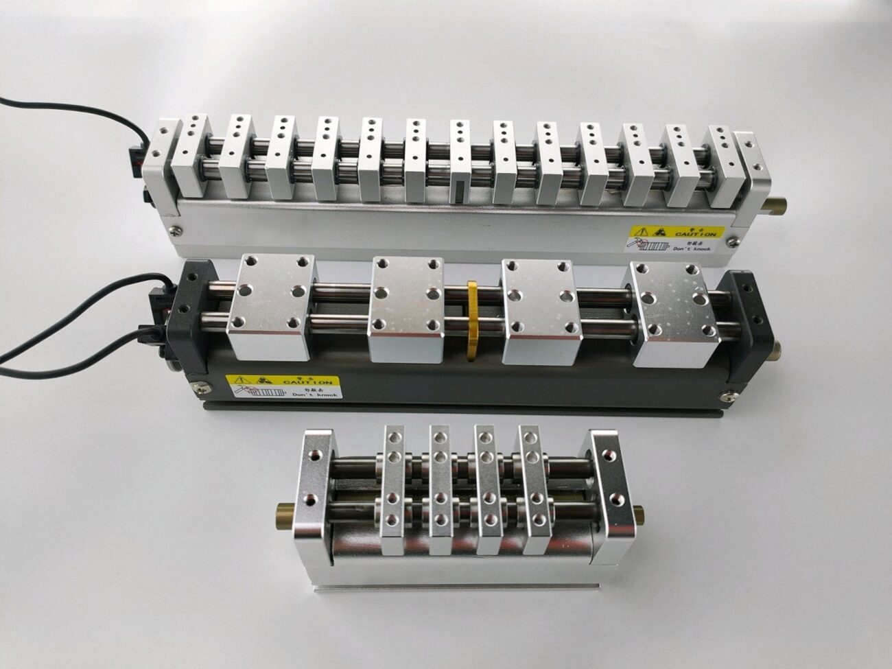
Variable Pitch Linear Modules Design: Mechanisms, Accuracy and Applications
Learn how to design a variable pitch linear module. Compare lead screw, timing belt, rack and pinion, and cam mechanisms, with practical guidance on motion accuracy, synchronization, servo selection, and pick-and-place applications. In automated assembly, the spacing between two pickup points is not always the same as the spacing between the parts being placed. A machine may need to pick up several components from a tray, move them closer together, and place them onto a PCB or fixture at a different pitch.
This is a typical application for a variable pitch module.
The principle sounds simple: move several heads and change the distance between them. The engineering challenge is making sure every head reaches the correct position, moves at the right time, and stays synchronized throughout the cycle.
A variable pitch mechanism can use a lead screw, timing belt, gear-and-rack transmission, cam mechanism, or linkage. Each option behaves differently under load and at speed. Choosing the wrong mechanism can lead to excessive backlash, vibration, inconsistent spacing, or a cycle time that never meets the original target.
This guide looks at how variable pitch mechanisms work, how to select a suitable design, and what to check before building a custom module.
What Is a Variable Pitch Module?
A variable pitch module changes the center-to-center distance between two or more moving units.
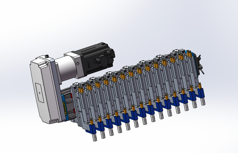
In industrial automation, these units are commonly suction heads, grippers, positioning slides, or workpiece holders. The module may use one motor to coordinate several heads mechanically, or multiple servo axes controlled electronically.
Consider a dual-head pick-and-place system. The two heads pick up components at a pitch of 30 mm, but the target positions are 50 mm apart. The mechanism must increase the pitch by 20 mm before placement.
If the two heads move symmetrically around a fixed centerline, each head travels 10 mm outward. The pitch changes by 20 mm, even though neither head travels the full 20 mm.
This distinction matters when calculating screw travel, actuator stroke, belt displacement, and installation space.
A variable pitch module is therefore not just a linear actuator with a longer stroke. It is a positioning mechanism whose output is defined by the relative movement of multiple points.
How Does a Variable Pitch Mechanism Work?
Most variable pitch systems contain four basic mechanical elements:
A drive source, such as a servo motor or stepper motor.
A transmission mechanism that converts input motion into coordinated displacement.
Linear guides that control the movement of each slider.
A mounting structure that maintains alignment under load.
A controller may also be required for programmable pitch adjustment, homing, synchronization, and position feedback.
The first design decision is whether the heads should move mechanically together or be positioned independently.
A mechanically linked system can reduce the number of motors and simplify synchronization. However, the movement relationship is largely determined by the transmission geometry.
A multi-servo system offers more flexibility. Individual heads can move to different positions, and motion profiles can be adjusted in software. The trade-off is greater control complexity, additional wiring, and the need to manage synchronization errors between axes.
For applications with a fixed and symmetrical pitch-changing pattern, a mechanical linkage may be sufficient. For machines handling multiple product formats, independently controlled servo axes may offer more flexibility.
5 Common Variable Pitch Mechanisms
1. Opposite-Hand Lead Screw
A bidirectional lead screw uses left-hand and right-hand threads to move two nuts in opposite directions.
When the screw rotates, the two nuts approach or move away from each other. With matched thread leads and a symmetrical arrangement, the mechanism can produce equal movement on both sides.
For a screw with lead , one full revolution moves each nut by , assuming the two thread sections have the same lead magnitude. The center-to-center distance between the nuts therefore changes by per revolution when they move in opposite directions.
This makes the relationship between motor rotation and pitch change relatively straightforward to calculate.
Where it works well
Precision assembly fixtures
Dual-head positioning modules
Inspection and measurement equipment
Applications requiring controlled, symmetrical movement
What needs attention
The screw lead accuracy, nut backlash, bearing support, and mounting alignment all affect the final positioning result. At high rotational speeds, critical speed and vibration can become limiting factors.
Thermal expansion also matters in precision applications. A long screw can change length as its temperature rises, shifting the position reference even when the motor encoder reports the expected rotation.
A preloaded screw nut can reduce backlash, but it does not eliminate screw lead error, structural deflection, or thermal effects.
2. Timing Belt and Pulley
A timing belt mechanism uses toothed belts and pulleys to coordinate the movement of multiple sliders.
The belt routing determines how each slider moves. With the correct arrangement, two heads can move in opposite directions while remaining mechanically synchronized.
Timing belts are attractive when the machine needs fast movement, a relatively lightweight structure, and a compact transmission layout.
Where it works well
Lightweight material handling
Electronics assembly
Packaging equipment
High-cycle transfer systems
What needs attention
A belt is not perfectly rigid. Its elasticity, pretension, span length, and load variation affect positioning behavior.
For example, a mechanism may perform well at low speed but show larger position deviations during rapid acceleration. The problem may not be motor resolution. It may be belt stretch, frame flexibility, or vibration.
Belt tension must also be set consistently. Too little tension can cause poor motion control or tooth engagement problems, while excessive tension increases bearing loads and may shorten component life.
For high-speed systems with moderate positioning requirements, a timing belt can be a practical choice. For very tight tolerances under changing loads, the complete error budget needs closer examination.
3. Gear-and-Rack Mechanism
A gear-and-rack system converts rotary motion into linear movement through meshing gears and racks.
With two racks arranged on opposite sides of a driving gear, the racks can move in opposite directions. The resulting pitch change depends on the gear geometry and rack arrangement.
This mechanism can provide high mechanical stiffness and support substantial loads when properly sized.
Gear backlash is one of the main sources of positioning error. When the drive reverses direction, clearance between the meshing teeth can create a delay before the output responds.
The mounting structure must also keep the racks aligned with the gear. Poor alignment can increase noise, wear, and uneven tooth loading.
For applications requiring repeatable positioning from both approach directions, consider backlash compensation, suitable gear quality, and the stiffness of the complete assembly.
4. Cam-and-Follower Mechanism
A cam mechanism uses a shaped profile or groove to control follower displacement as the cam rotates.
Unlike a simple screw or belt transmission, a cam can be designed to produce a specific motion relationship. The output may accelerate, decelerate, dwell, or follow another defined displacement profile during one revolution.
This can be useful in machines that repeat the same motion sequence thousands of times.
Where it works well
High-cycle assembly machines
Dedicated packaging equipment
Mechanisms with a fixed motion sequence
Compact machines with limited installation space
What needs attention
Cam profile design is more demanding than selecting a standard linear actuator. The designer must consider follower acceleration, contact stress, lubrication, wear, and manufacturing tolerances.
A cam can be an excellent choice for a stable, repetitive process. It is less attractive when the pitch range or motion sequence changes frequently, because modifying the mechanism may require a new cam profile.
5. Scissor-Linkage Mechanism
A scissor linkage uses connected arms to expand or contract multiple moving points.
The mechanism can produce a relatively large change in spacing within a compact structure. However, its output movement is nonlinear: the relationship between actuator travel and head displacement changes with the linkage angle.
This means the actuator force and mechanical advantage can vary across the working range.
Where it works well
Expandable gripping fixtures
Multi-point handling systems
Compact mechanisms requiring a large pitch change
Applications where multiple heads must move together
What needs attention
Joint clearance, link deformation, and alignment all affect repeatability. The mechanism should also be checked near extreme positions, where its mechanical advantage may change significantly.
A scissor linkage can save space, but it should not be selected based on compactness alone. Its geometry must work across the full operating range.
Which Variable Pitch Mechanism Should You Choose?
The best mechanism depends on the actual operating conditions rather than a general ranking of technologies.
Design requirement
Mechanism worth evaluating
Main issue to check
Controlled, symmetrical positioning
Opposite-hand lead screw
Backlash, lead accuracy, critical speed
Fast movement with lightweight heads
Timing belt
Belt elasticity, tension, vibration
High loads and rigid transmission
Gear and rack
Backlash, alignment, noise
Fixed high-cycle motion sequence
Cam and follower
Profile design, contact stress, wear
Large spacing change in a compact layout
Scissor linkage
Nonlinear motion, joint clearance
These are starting points, not absolute rules. A properly designed belt system may outperform an unsuitable screw system in a high-speed application. Likewise, a screw mechanism will not deliver high accuracy if its guides, bearings, and mounting structure are poorly aligned.
The entire mechanical system must be evaluated together.
How to Calculate Pitch Change and Required Travel
Before selecting a motor or transmission, establish the relationship between the commanded input and the actual pitch change.
For a symmetrical two-head system, let:
be the initial center-to-center pitch.
be the target pitch.
be the required pitch change.
Then:
If the two heads move equal distances in opposite directions, the travel of each head relative to the centerline is:
Example
A dual-head module must change its pitch from 24 mm to 64 mm.
The pitch change is:
For symmetrical movement, each head travels:
The mechanism must therefore provide at least 20 mm of travel for each head, plus any additional allowance required for homing, mechanical stops, tolerances, and the chosen motion profile.
This calculation applies only to symmetrical movement about a fixed centerline. If one head remains fixed, the other head must provide the full 40 mm change in spacing.
For a lead screw with equal and opposite thread leads, the pitch change per revolution is twice the thread lead magnitude. This relationship can be used to estimate the required screw rotation before motor speed and cycle time are considered.
How to Size the Drive System
Once the required travel is known, the next step is to calculate the force or torque needed to move the mechanism.
For a simplified horizontal motion, the required force can be estimated from:
Where:
is the effective moving mass.
is the required acceleration.
is the combined friction and other resisting forces.
This is a starting estimate. The final calculation should account for transmission efficiency, rotating inertia, external forces, shock loads, and an appropriate design margin.
For a screw-driven system, a simplified relationship between axial force and screw torque is:
Where:
is the required screw torque.
is the axial force.
is the screw lead per revolution.
is the effective transmission efficiency.
The actual motor torque requirement also depends on the transmission ratio, acceleration of rotating components, friction, and the dynamic characteristics of the system.
Do not size the motor using payload weight alone. A lightweight head moving at high acceleration can require substantial peak torque, while a heavier system moving slowly may have a more modest dynamic demand.
Also check the difference between peak torque and continuous torque. A motor may handle short acceleration peaks but overheat if the repeated duty cycle demands too much continuous torque.
For vertical axes, gravity and power-loss behavior must be considered separately. A conventional ball screw should not be assumed to hold a suspended load safely without a suitable brake or other load-retention measure.
What Determines the Accuracy of a Variable Pitch Module?
One of the most common design mistakes is treating motor resolution as the same thing as system accuracy.
A servo encoder may detect very small increments of rotation, but the final head position is also affected by the transmission, guides, mounting structure, feedback arrangement, and calibration.
The main sources of error include the following.
Backlash
Backlash creates lost motion when the direction of movement changes. It can come from screw nuts, gears, couplings, bearings, or joints.
If the application approaches the target from both directions, backlash should be measured and included in the positioning error budget.
Transmission Compliance
Belts stretch under load, while screws, shafts, brackets, and frames deform under force.
These effects may be small during static testing but become more noticeable during rapid acceleration or changes in payload.
Guide Alignment
Misaligned rails can increase friction and create uneven movement between heads. In severe cases, the mechanism may bind or wear prematurely.
Guide alignment and mounting flatness should be checked before attempting to correct motion problems through software.
Thermal Expansion
Temperature changes affect the dimensions of screws, frames, and other mechanical components.
For a precision module, repeated operation can shift the measured pitch even when the commanded motor position remains unchanged.
Synchronization Error
In a multi-servo system, each axis may track its own position command accurately while a small difference remains between the actual positions of the heads.
For this reason, measuring the relative distance between heads is often more useful than checking each motor encoder independently.
If the required tolerance is tight, establish an error budget and measure the actual output positions at several pitch settings. Testing should include both approach directions where reversal error is relevant.
Mechanical Synchronization or Multiple Servo Axes?
This decision has a direct effect on cost, flexibility, and commissioning time.
A mechanically synchronized module uses a shared transmission or linkage to define the movement relationship between heads.
Its main advantage is that synchronization is built into the mechanism. One drive can control multiple moving units, reducing the number of motors and control axes.
However, the movement relationship is less flexible. Changing the pitch range or movement pattern may require mechanical modification.
A multi-servo design allows individual axes to follow programmable position commands. It can support different pitch settings, asymmetric movement, and more complex operating sequences.
The trade-off is additional hardware and control work. Engineers must manage axis synchronization, homing, communication, tuning, and fault recovery.
For a dedicated machine with a fixed movement pattern, mechanical synchronization is often worth evaluating first. For a flexible production line that handles many product formats, independent servo control may be more appropriate.
The decision should be based on the required motion relationship, number of product formats, cycle time, and total system cost.
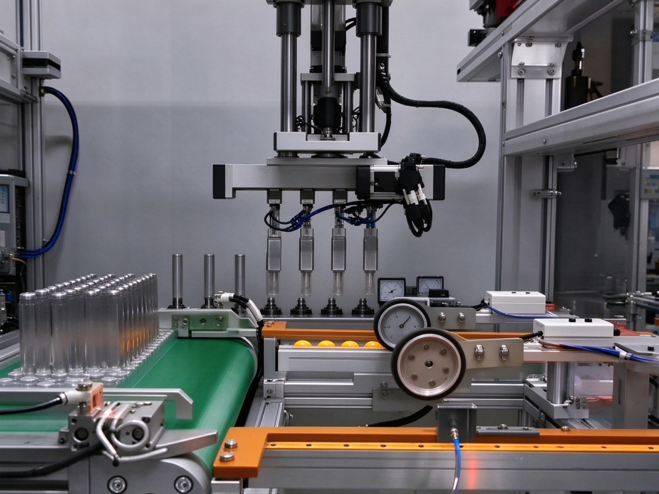
Variable Pitch Modules in Pick-and-Place Machines
Pick-and-place automation is one of the clearest examples of why variable pitch adjustment is useful.
A machine may pick several components from a tray or feeder at one pitch and place them onto a PCB or fixture at another. If the heads cannot change their relative spacing, the machine may need additional movements or separate handling steps.
A dual-head variable pitch module can combine several functions:
Servo-driven horizontal movement
Controlled pitch adjustment between pickup heads
Z-axis lifting and lowering
Optional head rotation
Vacuum pickup and release
Vision-based position correction
The pitch adjustment mechanism handles the relative spacing between heads, while the other axes perform pickup, placement, and orientation tasks.
The actual cycle time depends on how these movements overlap. A faster pitch adjustment does not necessarily improve overall throughput if vision processing, settling time, feeder access, or placement motion remains the bottleneck.
For this reason, evaluate the full machine cycle rather than measuring the pitch mechanism in isolation.
Variable pitch systems are also useful in automated packaging, multi-point gripping, electronic component handling, and fixtures that must accommodate different product dimensions.
Common Problems During Commissioning
A module that moves correctly during a no-load test may behave differently once installed in the machine.
Here are four issues worth checking during commissioning.
1. The heads do not maintain equal spacing.
Check the transmission geometry, mounting alignment, belt tension, joint clearance, and individual slider friction. In a servo system, compare the commanded and measured positions of each axis.
2. Positioning is inconsistent after reversing direction.
Inspect backlash in the screw nut, gear mesh, coupling, and linkage joints. Repeat the same positioning test from both directions to determine whether the error is related to reversal.
3. Vibration increases at higher speed.
Check mechanical stiffness, fasteners, moving mass, and transmission tension before changing servo gains. Excessive acceleration or an unfavorable resonance may also contribute.
4. Accuracy changes after extended operation.
Measure temperature, inspect lubrication and wear, and repeat the pitch test after the system reaches a stable operating condition. Thermal drift and changes in belt tension can affect long-term consistency.
A useful commissioning procedure records the commanded pitch, measured pitch, approach direction, payload, cycle rate, and operating temperature. This creates a baseline for troubleshooting and preventive maintenance.
What to Specify When Ordering a Custom Variable Pitch Module
When requesting a quotation from a variable pitch module manufacturer, provide more than the desired pitch range.
A useful technical specification includes:
Minimum and maximum center-to-center pitch
Number of moving heads
Required travel for each head
Payload per head and total moving mass
Required cycle time and acceleration
Positioning accuracy and repeatability
Mechanical synchronization or independent servo control
Available installation space
Mounting orientation and working environment
PLC, servo drive, and communication requirements
It is also worth clarifying how accuracy is measured.
For example, does the stated tolerance refer to the position of each head, or to the center-to-center distance between two heads? Is the value measured from one approach direction or both? Does it apply under the specified payload and operating temperature?
These details help prevent misunderstandings between the equipment builder and the module supplier.
A custom solution should be evaluated against the actual machine requirements, not simply against a headline accuracy figure.
Frequently Asked Questions
What is a variable pitch mechanism used for?
A variable pitch mechanism changes the spacing between multiple moving elements. Common applications include pick-and-place machines, electronics assembly, automated gripping, packaging, and multi-point material handling.
Which mechanism is best for a high-precision variable pitch module?
The answer depends on the load, speed, travel, and accuracy requirements. A preloaded screw-based mechanism may be suitable when stiffness and controlled positioning are priorities, but the guides, structure, feedback system, and calibration must also meet the required tolerance.
Can a servo motor control multiple pickup heads?
Yes. A servo can drive a shared mechanical transmission or control one axis within a multi-servo system. The choice depends on whether the heads need a fixed mechanical relationship or independently programmable positions.
How do you calculate the stroke of a variable pitch module?
First calculate the change in center-to-center pitch. For two heads moving symmetrically in opposite directions, each head travels half the required pitch change. If one head remains fixed, the other must travel the full pitch change.
Can a variable pitch module improve pick-and-place efficiency?
It can reduce unnecessary handling movements when pickup and placement pitches differ. The actual improvement depends on the full machine cycle, including head travel, settling time, vision processing, and feeder access.
What causes poor repeatability in a variable pitch system?
Common causes include backlash, guide misalignment, transmission compliance, structural deformation, thermal expansion, and inconsistent control behavior. The actual head positions should be measured before changing motor specifications or control parameters.
Final Thoughts
Designing a reliable variable pitch module starts with a clear understanding of how the heads need to move, not with the choice of motor.
Define the pitch range, calculate the required travel, establish the load and cycle-time requirements, and then select a transmission mechanism that suits the application. Check the guides and mounting structure carefully, and validate positioning accuracy under realistic operating conditions.
For simple, symmetrical movement, a mechanically linked design may provide the required performance with fewer drive components. For machines that handle different product layouts, a servo-controlled solution may offer greater flexibility.
If you are developing a multi-head pick-and-place machine or another automated handling system, start with the required pitch range, number of heads, payload, and target cycle time. These parameters provide a practical basis for selecting and designing the right variable pitch module.
Need a custom variable pitch solution? Contact our engineering team with your required pitch range, payload, head configuration, and positioning tolerance to discuss a suitable design for your equipment.
HCY Automation delivers integrated solutions across motion control, linear motion, robotics, machine vision, pneumatic systems, and precision gearboxes to help global manufacturers build smarter, faster, and more reliable production lines. Our engineering team helps you select and integrate the right motion control, robotics, and automation components for your specific application.