Discover the 6 critical stages of automated fiber coupling — from coarse alignment to UV curing. Learn how PILightning, FMPA, and multi-channel parallel alignment are cutting cycle times from minutes to milliseconds in 2026.
Automated Fiber‑Coupling Process Stages: From Lab Prototype to Mass‑Production Photonic Packaging
Photonic integrated circuits (PICs), co‑packaged optics (CPO), fiber arrays and quantum photonics systems demand ultra‑precise fiber‑chip interconnection. Even sub‑micrometer misalignment introduces severe optical insertion loss, degrading device performance and dragging down production yield. Manual fiber coupling, heavily dependent on skilled technicians, suffers from slow throughput, inconsistent repeatability and high labor costs.
Automated fiber‑coupling workflows resolve these pain points. Powered by multi‑degree‑of‑freedom precision positioning stages, real‑time optical power feedback, machine vision and closed‑loop alignment algorithms, standardized process stages enable stable transition from R&D validation to high‑volume industrial manufacturing.
This article breaks down every core automated fiber‑coupling process stage, compares typical challenges between active and passive alignment, and highlights practical considerations for your photonic packaging production line.
Why Automated Fiber‑Coupling Beats Manual Operation for Modern Photonics
Before diving into process phases, it is critical to understand why manufacturing engineers are shifting toward full automation.
Nanometer‑level repeatability: Single‑mode fiber coupling requires positioning precision down to tens of nanometers. Human operators cannot consistently hold such tight tolerances batch‑to‑batch.
Higher production yield: Automated closed‑loop alignment continuously tracks optical power peaks, minimizing coupling loss across hundreds of units.
Faster cycle time: Multi‑channel fiber‑array alignment cuts alignment time drastically versus manual tuning, supporting CPO and datacom module mass production.
Reduced reliance on specialized labor: Photonic packaging experts are scarce worldwide; standardized automated workflows lower skill‑barrier on production floors.
Full process traceability: Every alignment coordinate, power reading and curing parameter is logged for quality audit.
Common pain point: Many projects fail scaling because they directly copy lab‑style manual coupling parameters into mass‑production equipment. Automated fiber‑coupling needs well‑defined sequential process stages to bridge R&D and factory floor.
What Is the Automated Fiber Coupling Process?
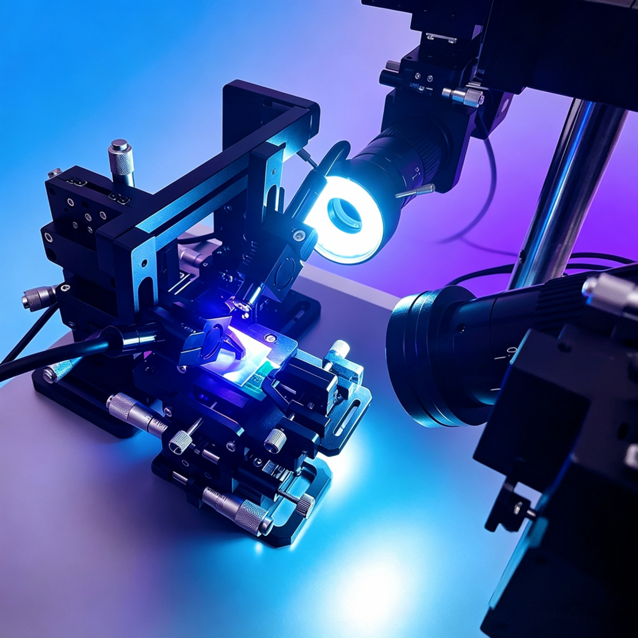
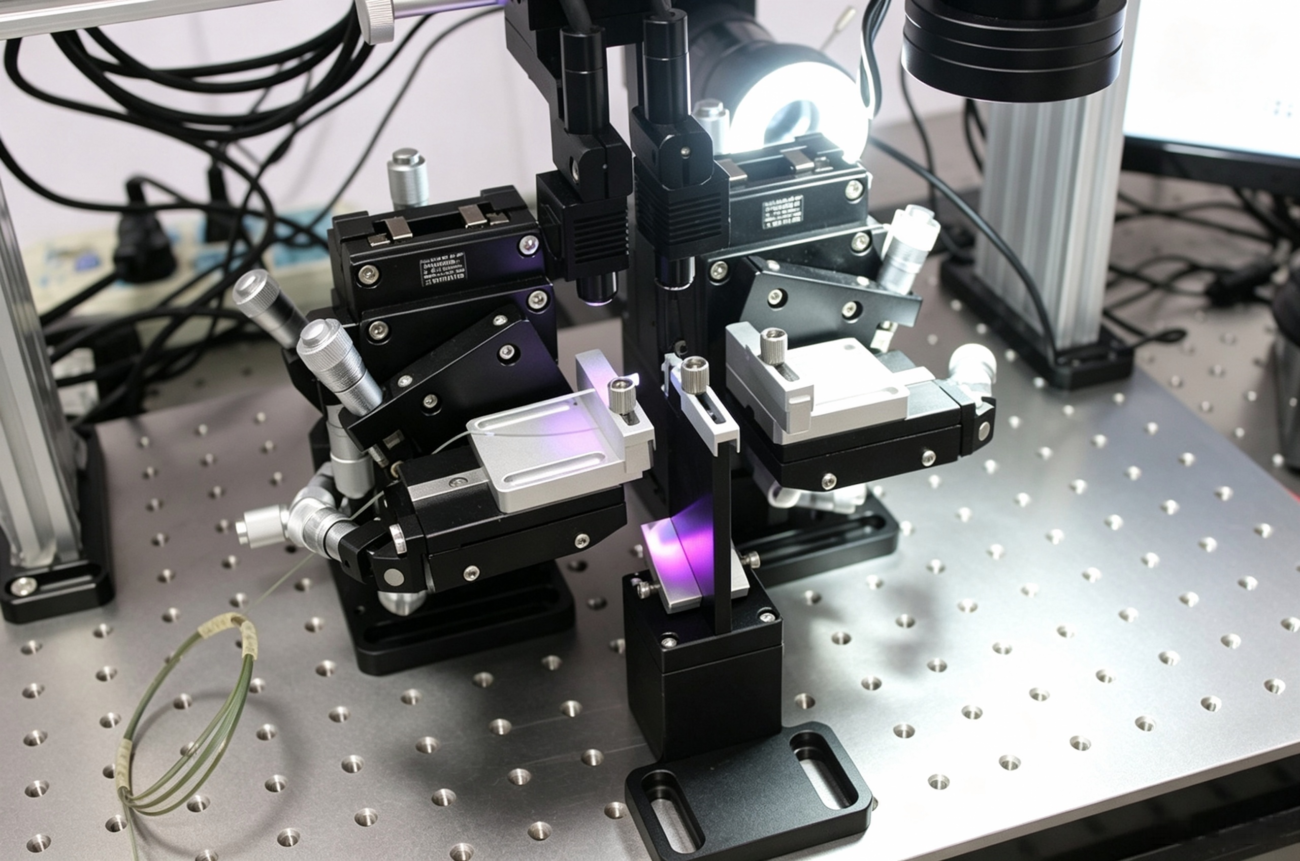
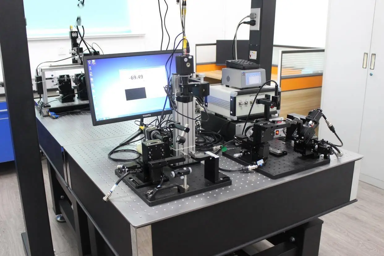
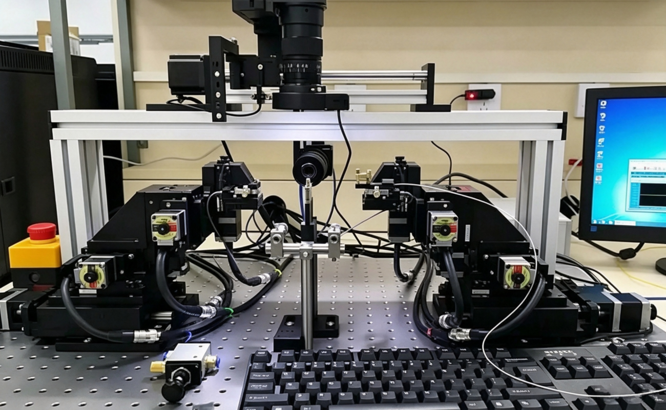
At its core, automated fiber coupling is the industrial workflow that uses precision motion platforms, machine vision, active optical feedback, and process automation to align optical fibers with waveguides, lasers, photodetectors, or photonic integrated circuits (PICs) — then permanently fix them in place.
Unlike manual alignment, where a technician tweaks micrometer heads while watching a power meter, automated fiber coupling executes the entire sequence — from loading to curing — under software control, achieving:
Sub-micron to nanometer precision (down to 0.1 nm with piezo stages)
Cycle times measured in seconds (not minutes)
Repeatability of 0.02 dB coupling loss across thousands of units
Unattended batch operation for high-volume production
The process is not a single action. It is a 6-stage pipeline, each with distinct hardware, software, and quality requirements.
The 6 Critical Stages of Automated Fiber Coupling
Stage 1: Loading & Coarse Alignment — Getting in the Ballpark
Objective: Bring the fiber or fiber array within the “capture range” of the fine alignment system.
How it works:
A robotic gantry or pick-and-place system loads the fiber stub, fiber array unit (FAU), or optical component onto the alignment station.
Machine vision cameras perform pattern recognition or fiducial mark detection to identify the fiber core and waveguide coupler positions.
Motorized XYZ stages execute coarse positioning — typically within ±10–50 µm of the target — using pre-calibrated motion recipes.
Key hardware:
Gantry robots with linear motors
Machine vision cameras (visible or IR)
Motorized XYZ stages (±1 µm resolution)
Custom pick-tips and substrate holders
Why it matters: Without accurate coarse alignment, the fine alignment stage wastes precious seconds (or fails entirely) searching for optical signal. In high-throughput production, every second of coarse alignment time directly impacts UPH (units per hour).
Breakthrough: Advanced vision algorithms can now pre-align to within ±2 µm in under 200 ms, shrinking the search space for Stage 3 by orders of magnitude.
Key Challenges in Automated Fiber‑Coupling Process Implementation
Even mature hardware meets real‑world manufacturing obstacles:
Curing‑induced position drift: UV glue shrinkage remains one top cause of post‑curing coupling loss rise.
Multi‑channel crosstalk: Tuning one fiber channel shifts adjacent channel performance for dense fiber arrays. Parallel optimization algorithms are required.
Thermal drift: Environment temperature fluctuation moves nanoscale alignment points; thermal stabilization or continuous closed‑loop compensation is necessary.
Trade‑off between cycle time and yield: Aggressively shortening alignment scan time risks missing true optical power peak. Process engineers need to balance throughput and yield targets.
Transition gap from R&D to mass production: Lab‑optimized coupling parameters often cannot replicate on production equipment; process parameter re‑validation is mandatory before volume ramp‑up.
Main Industrial Application Scenarios for Automated Fiber‑Coupling Stages
These standardized process stages serve fast‑growing photonic industry segments:
Silicon photonics & CPO packaging: Fiber‑to‑PIC coupling for AI data‑center optical engines, high‑speed transceivers.
Fiber array assembly: Multi‑channel FA coupling for coherent communication, WDM components.
Quantum photonics: Ultra‑stable low‑loss fiber coupling for quantum chips, where tiny loss degrades quantum fidelity.
Laser packaging: Laser diode to fiber coupling for industrial laser and sensing devices.
Medical optics & aerospace photonics: High‑reliability optical component assembly requiring full process traceability.
The 3 Tiers of Automation: Which Workflow Is Right for You?
Tier
Configuration
Best For
Precision
Throughput
Cost
Manual
Hand-operated micrometer heads, visual monitoring
R\&D, university labs, prototyping
1–10 µm
1–2 UPH
\$500–\$3,000
Semi-Automated
Motorized stages + PC workflow software, operator loads/unloads
Mid-volume optical device factories, multi-variety production
5 Megatrends Reshaping Automated Fiber Coupling in 2026
1. From Minutes to Milliseconds: The Algorithm Revolution
Traditional meander first-light searches take 30–60 seconds per fiber. PILightning and FMPA have reduced this to <500 ms — a 100×+ speedup that makes high-volume CPO production economically viable.
2. From Single-Channel to 64-Channel Parallel Alignment
As parallel optics replaces single-fiber transceivers, alignment systems must scale linearly in channels without scaling linearly in time. NxM technology makes this possible.
3. From Die-Level to Wafer-Level Testing
Wafer-level automated probing — aligning fibers to hundreds of die sites on a 300 mm wafer — is 30% faster than die-level testing and saves an estimated $350 million annually for high-volume fabs.
4. From Open-Loop to AI-Closed-Loop
Machine learning is now embedded in alignment controllers for predictive drift compensation, anomaly detection, and autonomous parameter optimization — reducing human intervention to near zero.
5. From Permanent to Modular
Detachable connectors and modular fiber arrays are emerging as alternatives to permanent epoxy bonding, enabling field replacement and wafer-level testing without committing expensive optical engines to irreversible assembly.
The Complete Automated Fiber Coupling Equipment Stack
Subsystem
Function
Key Suppliers
Precision motion
Nano/micro-positioning stages, hexapods, gantries
PI, Aerotech, SmarAct, ALIO
Machine vision
Fiducial detection, edge recognition, IR alignment
Basler, Cognex, Keyence
Optical metrology
Power meters, OSAs, polarization controllers
Thorlabs, EXFO, Yokogawa
Process modules
Epoxy dispensing, UV curing, laser welding
Dymax, Nordson, IPG
Control software
Alignment algorithms, recipe management, MES integration
PI (FMPA/PILightning), custom LabVIEW/Python
Fixtures & consumables
Fiber arrays, V-groove substrates, adhesives
Senko, US Conec, NTT
What is automated fiber coupling?
Automated fiber coupling uses multi‑DOF precision motion stages, machine vision and optical power feedback to accurately align optical fibers with photonic chips or other optical components, replacing manual tuning for photonic packaging manufacturing.
What are main stages in automated fiber‑coupling process?
The 6 critical stages are: (1) Loading & Coarse Alignment — robotic pick-and-place + vision-based pre-positioning; (2) Vision-Based Pre-Alignment — feature matching to within ±1–5 µm; (3) Active Fine Alignment — real-time power feedback optimization; (4) Multi-Channel Parallel Alignment — simultaneous NxM channel optimization; (5) Optical Performance Verification — stability, spectral, and PDL testing; (6) Permanent Fixation & Curing — epoxy dispensing + UV cure with active tracking.
How long does automated fiber coupling take?
Manual alignment: 5–15 minutes per fiber
Semi-automated active alignment: 30–120 seconds per fiber
Fully automated with PILightning/FMPA:<500 ms for first light + <1 second for full multi-channel array alignment
What is active alignment vs. passive alignment in fiber coupling?
Passive alignment uses mechanical features (V-grooves, alignment pins) to position fibers without optical feedback. Faster and cheaper, but limited to ~±1 µm tolerance. Best for high-volume, lower-precision applications.
Active alignment uses real-time optical power feedback to optimize position before bonding. Achieves sub-50 nm precision and coupling losses below 0.5 dB. Essential for 800G+, CPO, and silicon photonics.
What is the difference between 6-axis and 12-axis fiber alignment systems?
6-axis (single-sided): Controls X, Y, Z, θx, θy, θz for one fiber. Suitable for simple edge coupling or single-channel devices.
12-axis (dual-sided): Two independent 6-axis platforms — one for input, one for output. Required for wafer-level probing, dual-sided PIC testing, and complex packaging with simultaneous input/output alignment.
Is active alignment better than passive alignment for PIC production?
Active alignment delivers better loss performance and tolerates wider component mechanical variations, which dominates silicon photonics and CPO pilot‑to‑volume production. Passive alignment excels for high‑volume multi‑mode scenarios with tight mechanical component specs.
How does active tracking during epoxy cure work?
During UV curing, adhesive shrinkage and thermal transients can shift the fiber by 100+ nm. Active tracking continuously monitors optical power and commands real-time piezo corrections to maintain peak coupling efficiency throughout the cure cycle. This minimizes post-bond shift to <50 nm.
What is NxM alignment?
NxM alignment is a technology that simultaneously optimizes N inputs and M outputs across P degrees of freedom — with alignment time virtually independent of N, M, or P. A 64-channel CPO engine aligns as fast as a single-channel device.
What is PILightning?
PILightning is PI’s breakthrough first-light detection algorithm that solves the initial signal search problem orders of magnitude faster than traditional meander scans — in some scenarios, achieving 500× improvement in first-light capture time.
Conclusion
Automated fiber‑coupling is not simply buying alignment hardware. Real manufacturing success relies on executing standardized sequential process stages: from pre‑alignment cleaning and fixturing through coarse vision positioning, active peak‑search alignment, anti‑drift locking, shrinkage‑compensated UV curing, to final optical quality inspection.
As silicon photonics, CPO and quantum‑photonic markets expand, mastering these process stages allows OEMs and contract manufacturers to smoothly move photonics devices from laboratory prototype toward stable high‑volume mass production.
If you are evaluating automated fiber‑coupling solutions including 6‑DOF alignment stages, fiber‑array alignment platforms or photonic packaging equipment, our team can share practical process reference for your device specifications.
HCY Automation delivers integrated solutions across motion control, linear motion, robotics, machine vision, pneumatic systems, and precision gearboxes to help global manufacturers build smarter, faster, and more reliable production lines. Our engineering team helps you select and integrate the right motion control, robotics, and automation components for your specific application.